Portable PCB Reflow Plate
Why Reflow?
Reflow soldering is the technique used for soldering surface-mount components in electronics mass production. Instead of soldering individual joints with a hot iron, the user follows the following steps:
Mask off and apply a layer of solder paste (solder micro-balls in tacky flux) to the PCB pads
Place components onto board
Heat board along a set temperature profile, soldering paste into consistent joints.
There are 3 main benefits of reflow soldering. Firstly, it allows you to solder chips that would otherwise be with inaccessible pads, like BGA packages, and achieve higher component density in PCB designs (since you don’t have to fit a soldering iron in between components). Secondly, it improves the quality and consistency of solder joints. Finally, it makes assembly much quicker on complicated boards, as each additional component only adds the time necessary to place it on the paste.

reflow gif courtesy of sparkfun

Reflow curve for SMD281AX 63/37 solder paste

Comparison of design to existing options on spreadsheet link
Baselining
There’s a few existing options, but all are either DIY and underoptimized or industrial-esque and massive. There’s one exception: the MHP30M by sainsmart, which is compact and well engineered, but too small for functional boards at 3cmx3cm!
Overall, there’s a huge space for an open-source, DIY, semi-compact reflow plate at or below $100.
Design
The core electronic components necessary are a heating element, a sensing element, a microcontroller, and a user interface.
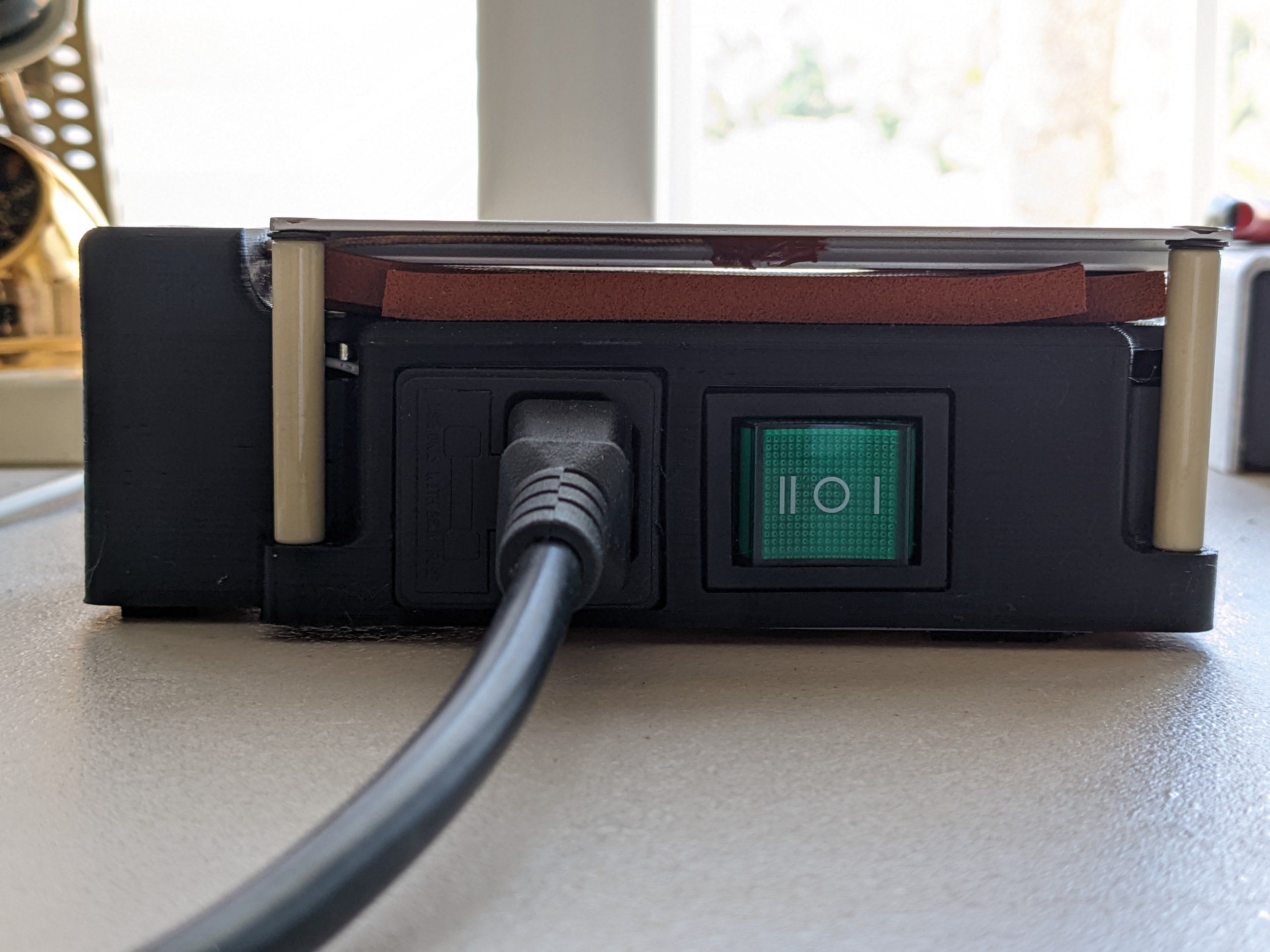
I found the flat AC hot plate used in Electronoobs’ tutorial was indeed the best for something of that size. However, in his design it was ungrounded and driven by an unfused solid state. In this case its safest to use an electromagnetic relay, since those fail open rather than closed (like the SSR does), grounding on the hotplate, and a fused plug. For the DC components, I wanted to use a high-accuracy thermocouple and amplifier pair,a large screen to display reflow curves in a complete UI like the T 962 oven, and a quiet Noctua fan to reduce noise.
Aliexpress component shipping gave plenty of time for CAD, so I had time to make a detailed, compact enclosure for all the electronics.
I tested the electronics on breadboards to check the SPI bus and thermocouple accuracy.

Block diagram shows connectivity of all electronics components. I had to check the Arduino wouldn’t run out of pins!

BOM Components: I designed it to use kit comonents I had on hand, so I only factor in the portion of those I use since they’re interchangable.


Plate hidden & shell transparent to show design

Electronics Wiring
Assembly & Wiring
There were a few new DFA changes I made for this project. To reduce wiring mess, I routed all the data connections underneath the Arduino, which required soldering outside the enclosure. I also used plastic-tapping screws for mounting everything except the bottom plate.
I did run into a few issues during assembly though:
Continuous flexing of solid-core wires attached to microcontroller broke 2 microcontroller traces (and 2 wires), which were very difficult to debug.
OLED mounting system broke and plastic-tapping screws had to be improvised
microUSB didn’t line up, forcing me to file out the hole wider
General wiring mess
Code & UI
The programming was by far the most time-consuming aspect of this project, exclusively due to the 128x64 pixel OLED UI.
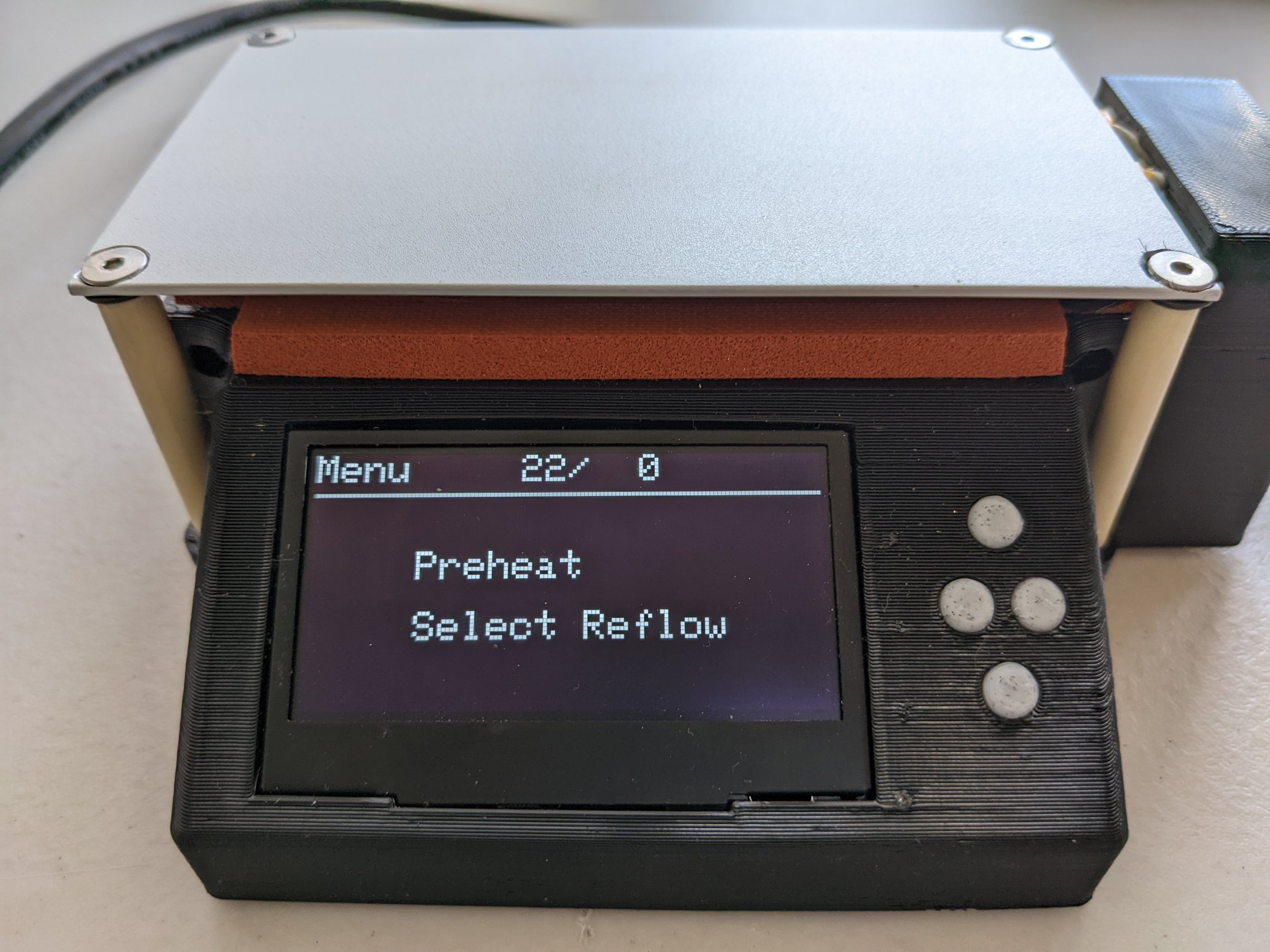
The code switches between 4 states, each pertaining to a different UI screen.
Menu for selecting preheat or reflow mode
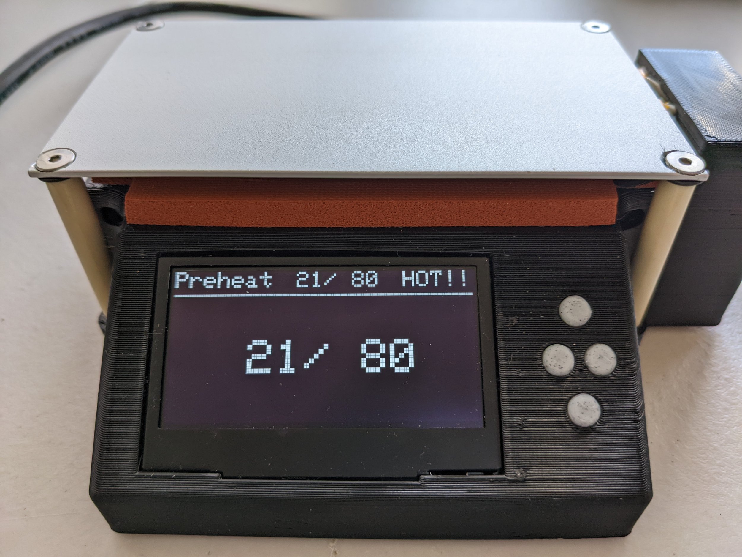
Preheat mode for setting and heating to fixed temps
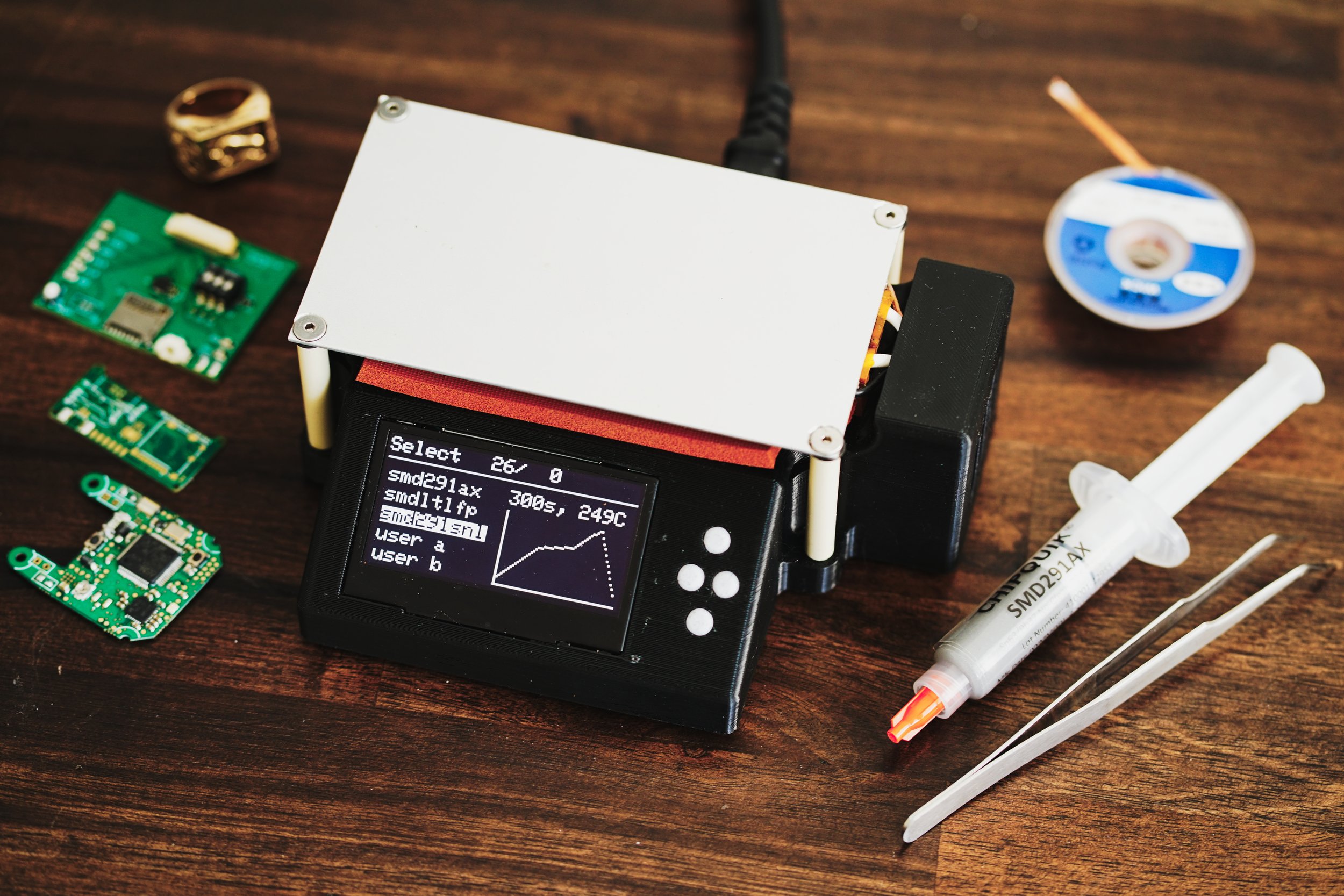
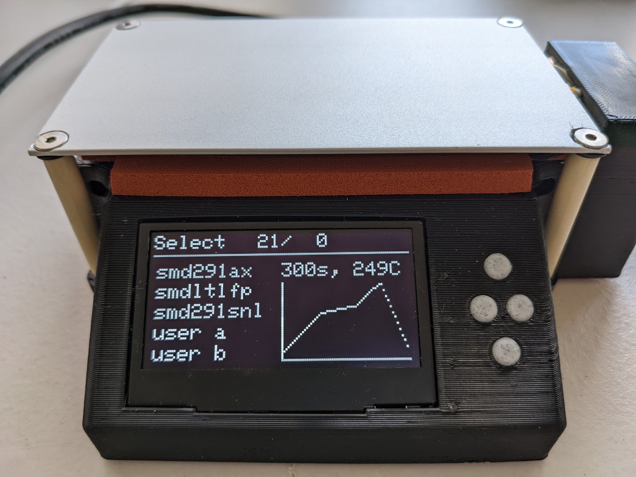
Selection screen for selecting among 5 preprogrammed reflow curves
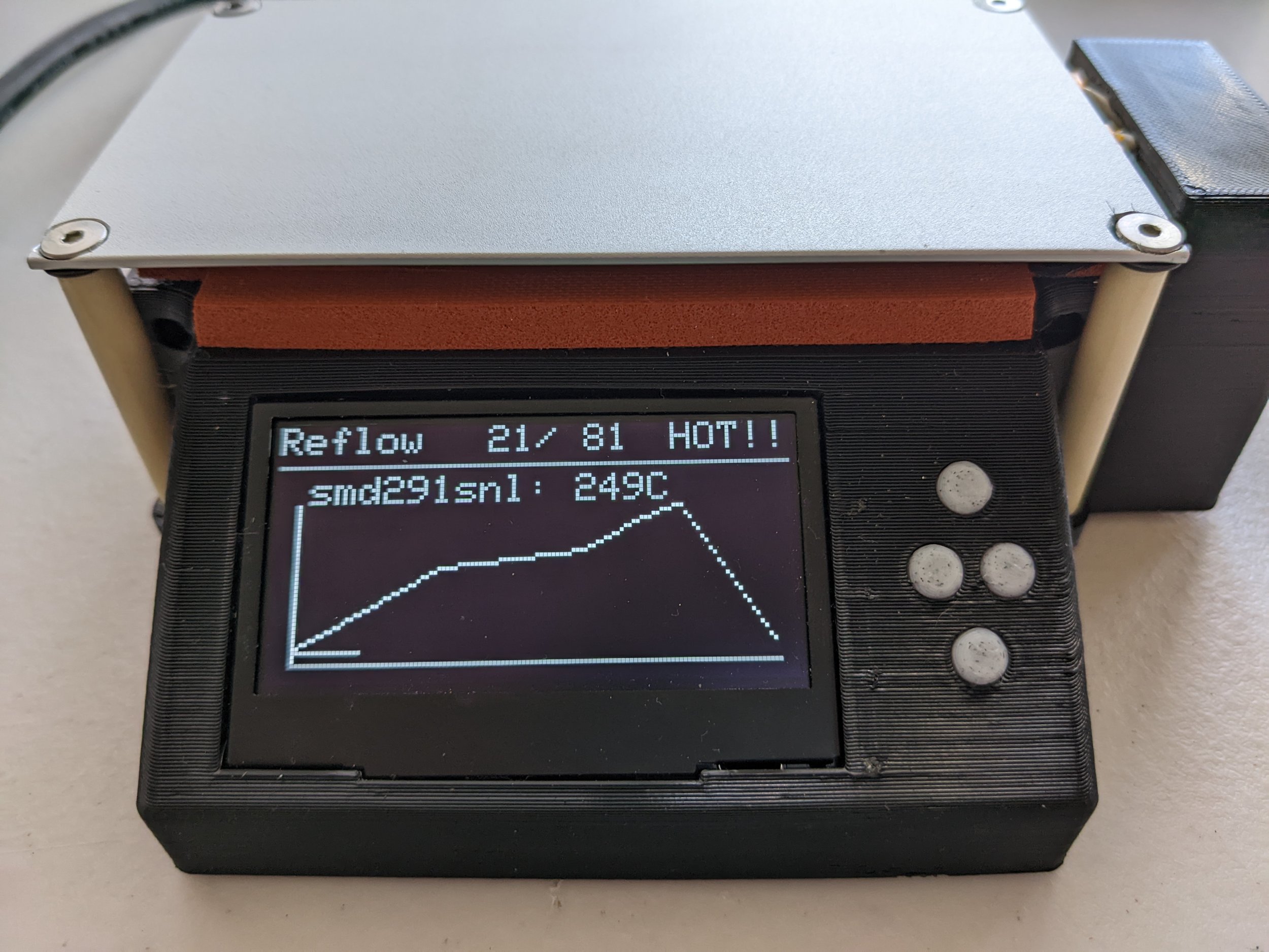
Reflow screen graphing reflow curve against achieved temperature history
Additionally, when variables change the status bar showing the state, current temp, set temp, and a blinking “HOT!!” if the screen is hot.
The current code is a little over 500 lines. Originally I started programming my own state machine, which got very messy and I ended switching to a preexisting library. I originally was running PID temperature control, but I ran into issues and ended up reverting to a logarythmic-proportional control temporarily.
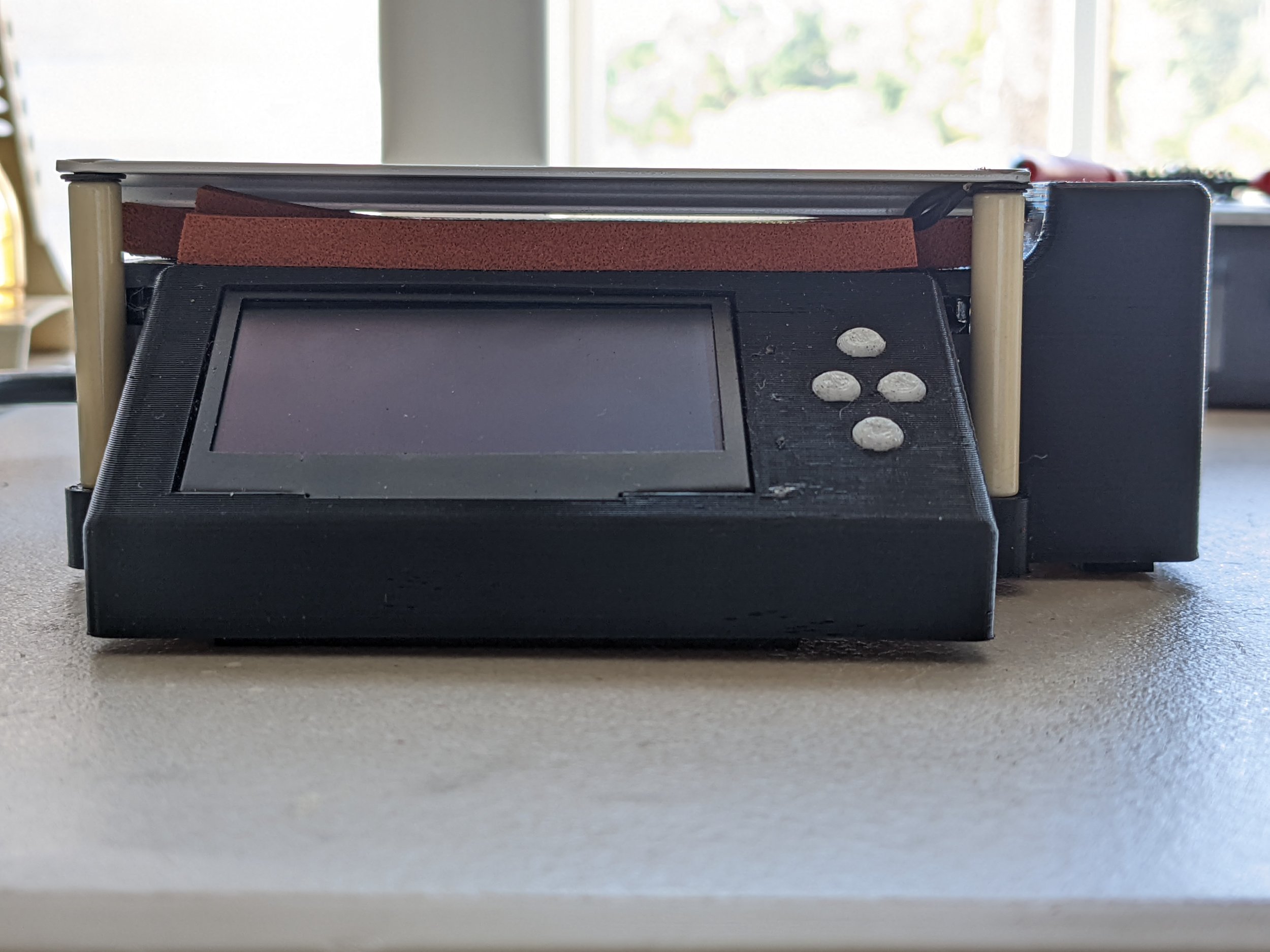
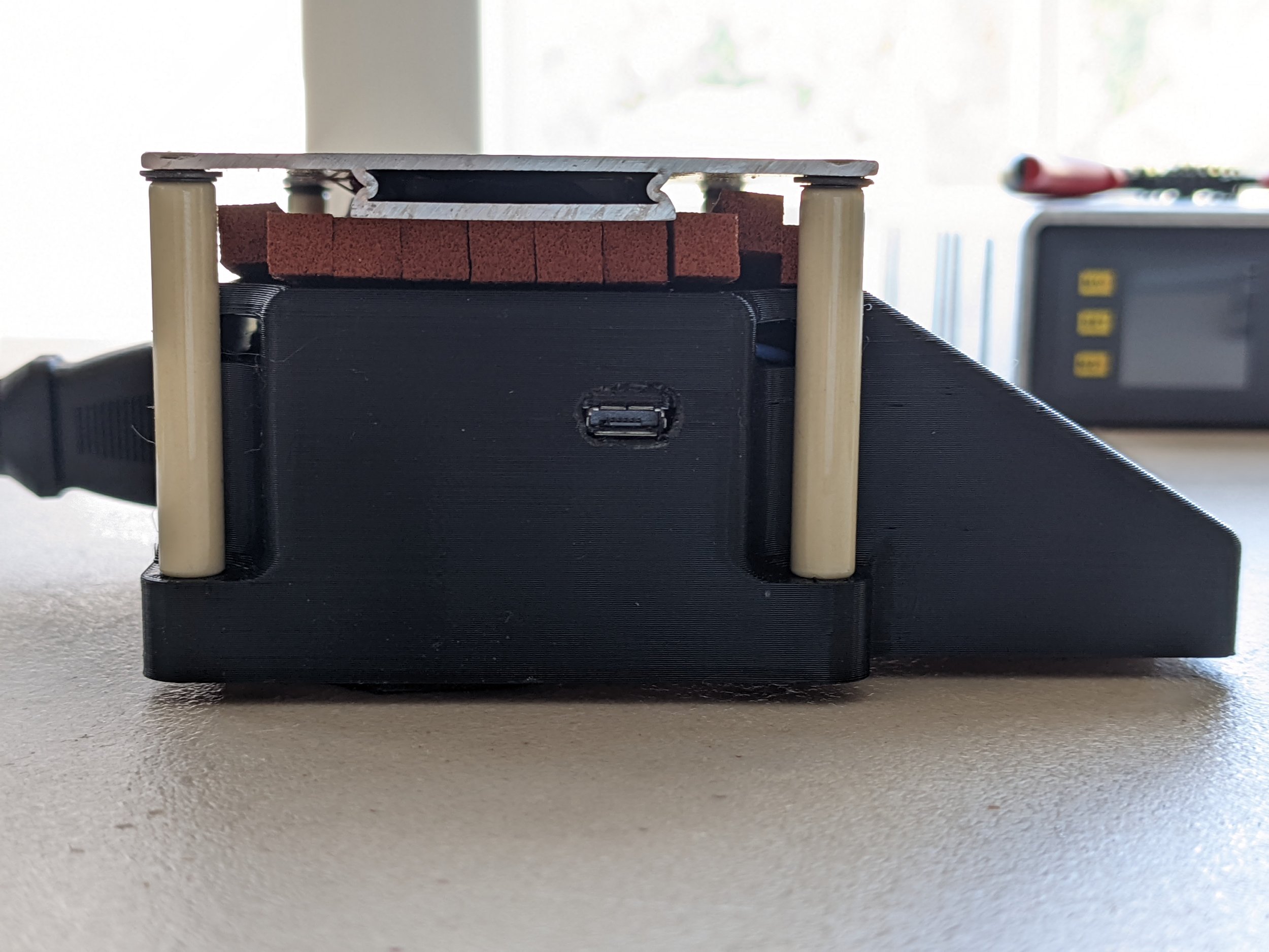
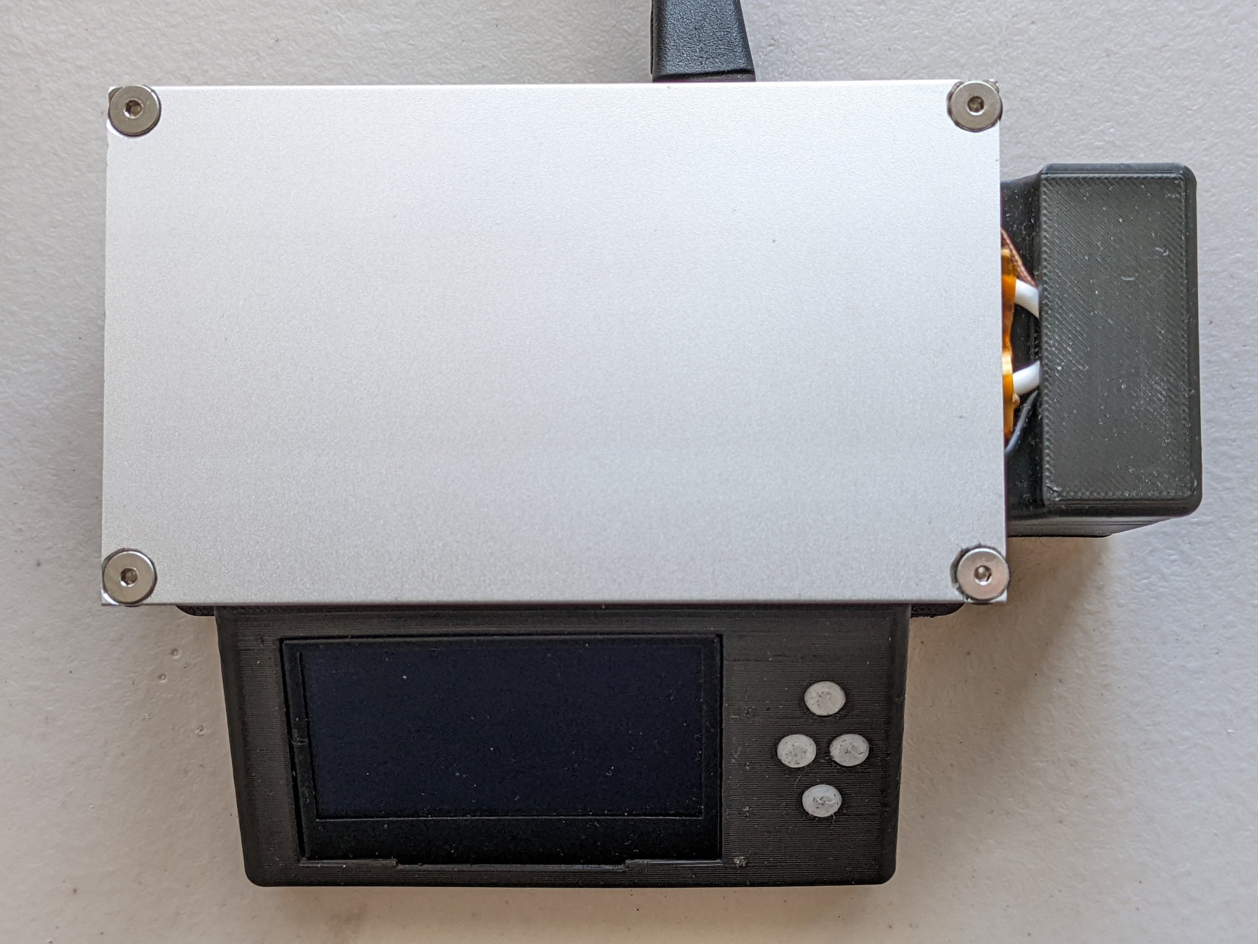
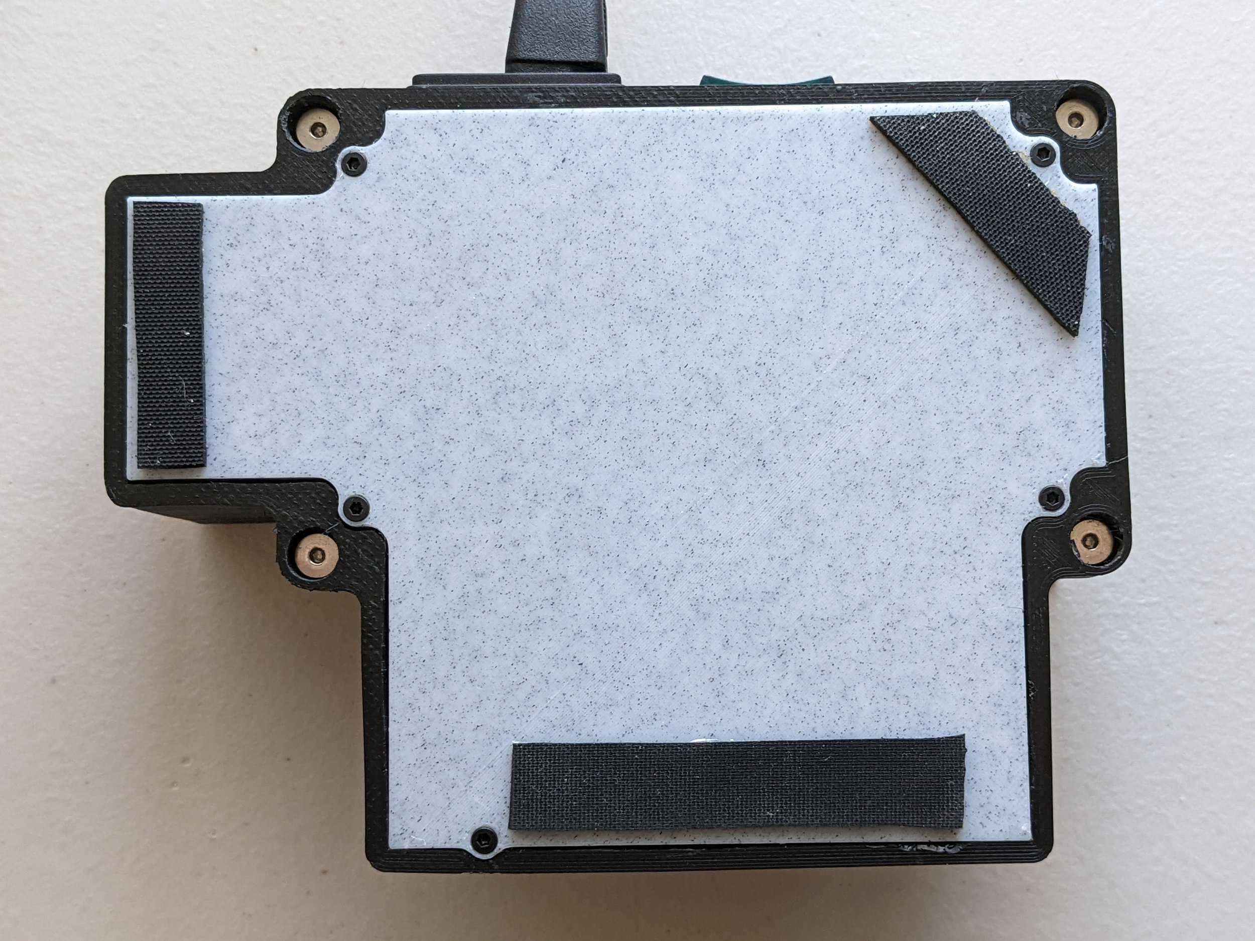
Completed Housing
Really happy with how the housing came out overall. The print was a bit messy and the fitment of the bottom plate required a bit of sanding.
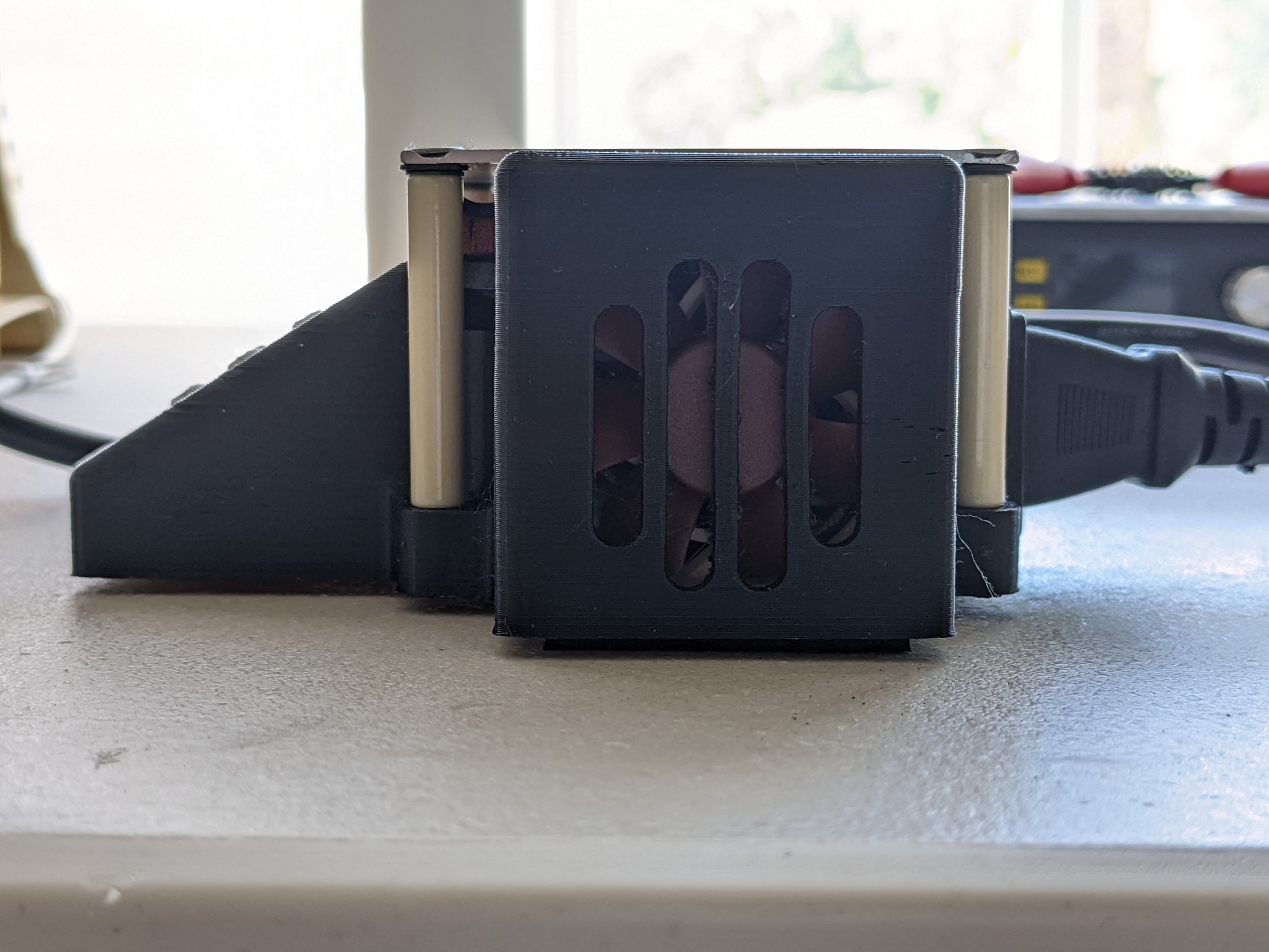
I was very worried about the screw countersinks on the holt plate and the efficacy of the standoff-cooling fan vents but those both worked well.
Thermal Safety
I also coded in a few checks that cut off heating if thermocouple readings aren’t responding to heating and used a electromagnetic relay since they tend to fail open rather than closed.
The ceramic standoffs ensure plastic standoffs never get too hot, but in the case they did I performed a quick flame test to see how the enclosure would fare in the event of unsupervised thermal runway. The overall result is not good… but the carbon fiber nylon fared much better than PLA.
However, thermal image capture proves that the plastic doesn’t get that hot, even under 5 minutes of 250C setpoint.

Flame Test:
All materials burned under direct flame, but insulation foam proved flame resistant.

Results of Flame Test
From top to bottom as clamped: Insulation foam, silicone stranded grounding wire, PLA filament, Carbon-fiber filled nylon filament.

Plastic gets up to ~50 degrees C, while ceramic columns

Solder test on a couple pads of an old PCB (tagconnect for scale)
Future Improvements
I’m really happy with how this turned out: It outperforms everything comparable, especially since I value performance & compactness most. Definitely ended up more expensive than I hoped, but I mostly assign that to buying high-temperature components.
Housing cut into extra section to allow simplified hot plate replacement
Housing reprinted in carbon-fiber nylon for increased glass transition temperature
Reimplement PID control to reduce steady state error and undershoot of peak solder temp
Ability to edit reflow curves without uploading code
Filter mesh on input fan
I don’t know how many of these changes I’ll end up implementing or how many of these will get baked in to a v2 with an SD card for storing reflow curves, an ESP-32 for future connectivity, larger fan for cooling, support for a glass cover to reduce escaping heat, and custom PCB for simpler assembly & further reduced form factor. I’d estimate I could halve the component cost doing something like this, making it price-competitive enough to sell as a kit potentially! We’ll see when I have time to make a v2.
Open-Source Files
The source files are available in a github repo. It’s tentatively licensed as GPL to promote people open sourcing their projects too :)
If you’re looking to build it, the files are also available in .step and stl format.