
3D Printer Reliability Upgrades
My Printer
I’ve been using a personal Artillery Sidewinder X1 FDM printer for my projects since mid-2019.
It’s a great printer but has a major reliability flaw: it relies on FPC ribbon cables, which have contacts that wear out and fail over time. Sidewinder users on reddit, youtube, thingiverse, and printer-specific sites are stuck troubleshooting the issue. The viable solution most attempt is first trying electrical contact cleaner. When that doesn’t work, replacing the ribbon cables and the PCBs they connect to is the only way to go.

Sidewinder X1 printer: cheapest printer w/ 30cm^3 build volume & direct drives

Corroded contacts on both the cable and connector.

Bypass wires hanging from the x axis rail

View of bypass wires soldered to hotend PCB
My printer has had contacts become corroded over the course of the last 2.5 years. To correct this, I soldered wires bypassing the ribbon cables with manual 24awg stranded wires. However, these wires occasionally got caught in the x-axis, and when more contacts failed I decided not to solder more bypass wires as a result.
Since the common solution costs $40-$50 and takes a month to arrive (PCBs from banggood), but still just renews the same failure-prone system.
I thought it would be fun to make a more permanent solution using the same budget and timeframe.
Sourcing & EDA
I initially explored ‘using’ existing consumer connectors like HDMI or USB-C to carry the current for the hotend. However HDMI & USB data contacts only carry .5A and the hotend requires 3A @ 24V, which combined with the stepper motor, fans, and sensors taking up other pins would’ve made pin allocation really tight. It also would still leave the contacts open to corrosion due to being used near operational limits in a motion system.
This all forced the move to a soldered cable, and luckily digikey stocked a 10 strand 24awg cable that fit in the channels of the extruded frame. That means one cable would carry electrical connections to the x-axis while a second cable would attach to the hotend. Each cable costs $11, so inculding shipping the cabling costed $27.
I started mocking up these boards in Altium CircuitMaker since I am very familiar with Altium Designer, the enterprise version of Altium’s software. However, I discovered early on that there’s no function for making custom component libraries in CircuitMaker along with no help documentation (since the product is new)!
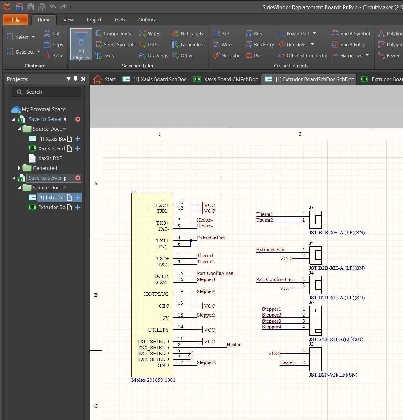
Circuitmaker schematic editor: quick, easy to use, and fast to place components from the integrated library.
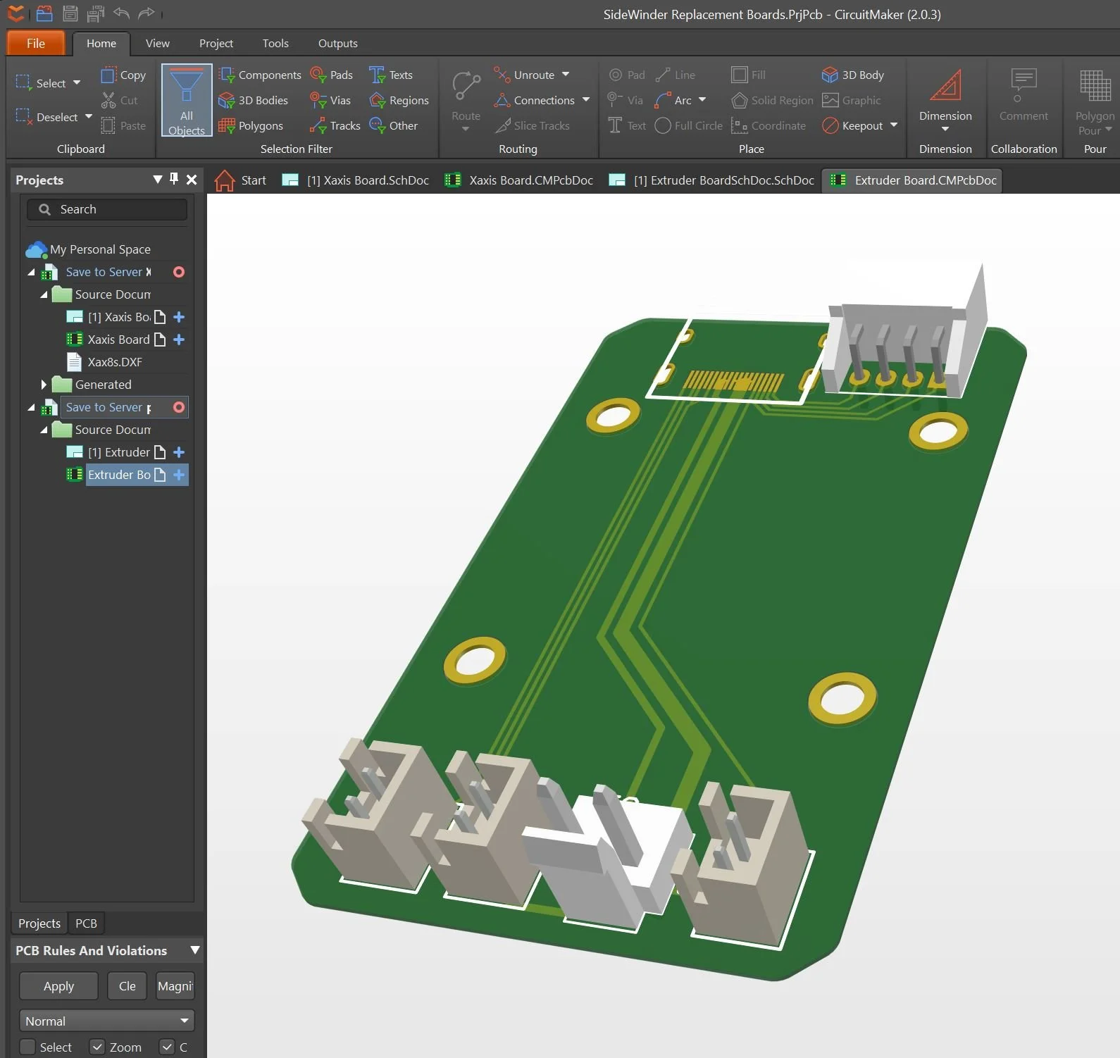
Board editor was familiar to me and has a convenient 3D mode. Too bad it doesn’t have critical functionality like documentation or custom libraries.
Switch to KiCAD
I immediately started transitioning my work over to KiCAD, the best FOSS EDA. Despite not having used it in years, it was super easy to get up and running, and despite lacking some creature comforts, I actually prefer the way it handles libraries to Altium designer. It even hooks up with Library Loader, which means most mouser components can be quickly added.
My one only gripe coming from Altium is the multi-window style of interface, where there’s separate windows for libraries, schematics, boards, and project management gets really messy.
I ordered the PCBs from JLCPCB since PCBGogo was closed for CNY, which totalled around $30 including shipping for 5 copies of each.
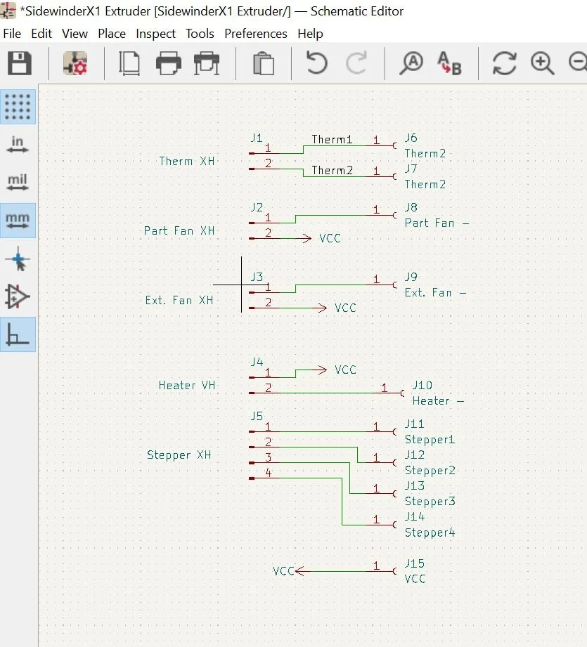
Accidentally made the schematic SUPER ugly by using the wrong symbol library.

PCB layout was pretty comfy after setting up hotkeys.

New PCBs and cables

Soldered Base PCB with standoffs installed

Old PCBs (top) vs New PCBs (bottom)
Extruder PCBs (left), base PCBs (middle) connect motherboard JST cables to new cabling, X-axis PCBs (right)

Soldered extruder PCB (left) and installed X axis PCB (right)
PCBs & Assembly
New PCBs came a little less than 2 weeks later and they came out great! The via & general feature alignment is great and the silkscreen and soldermask are consistent. Also the blue matches the sidewinder well :)
Desoldering and transitioning over the components from the original PCBs was smooth and the PCBs fit well.
The new 10 conductor 24awg cables were much more work to solder. The zip-tie attachment and strain relief worked well. The hole size I chose was a bit oversized which made soldering the individual conductors difficult, especially given I was keeping the cables long in case I needed to edit the attachment order. This turned out to be prudent as I ended up needing to switch the order of the X axis stepper motor.
Mounting the PCBs turned out well and the X-axis stepper, homing sensor, and extruder fans worked properly with no extra configuration.
Motherboard Failure / Marlin Edits
Unfortunately despite connectivity tests showing correct connections & no shorts, the hotend thermistor failed to heat. I’ve had problems with it before that I assumed were due to poor electrical contact, but upon wiring it directly to the PCB it still would not read: the analog port was fried.
Fortunately there’s a spare analog port, but using it requires editing the Marlin firmware the main board runs on. In the past I uploaded new firmware using the advice from this printer guide site, but I haven’t had to edit it before.
Download and install VSCode from Microsoft (Arduino fails to compile depending on the directory length)
Install Auto Build Marlin for VSCode, which includes the platform.io extension necessary to build the Arduino project (alternatives here)
Download the standard release of digant73’s latest Sidewinder fork of Malin firmware
Open VSCode, click the ‘Auto Build Marlin’ sidebar, then open the unzipped download folder
Using the ‘explorer’ sidebar open <folder>/Marlin/src/pins/pins_RAMPS.h
Edit the pin definitions under ‘temperature sensors’, TEMP_0_PIN is the default hotend port, TEMP_1_PIN is the spare, and TEMP_2_PIN is the bed
Go back to the Marlin tab and confirm that the machine name, board, and environment are ‘Sidewinder X1’, ‘MKS GEN L’ and ‘mega2560’ respectively before hitting ‘Build’
Unplug your sidewinder X1 from the wall, open the bottom, and unplug the touchscreen data cable as shown in the image.
Plug your computer into the mainboard via USB-Type B cable (as used in arduino uno) and hit upload.
Update the TFT / Touchscreen firmware as normal using digant73’s TFT firmware as per instructions on that page (put on SD card and insert before power-on)
Now the firmware is switched over to read from the unused thermistor port!

Yellow analog read port originally used for hotend thermistor was burnt out, so had to switch to unused red analog read port.
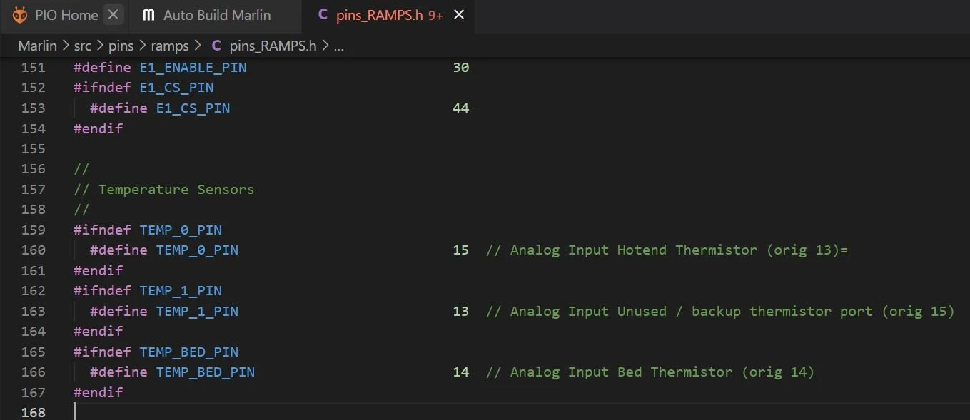
New upload code: thermistor remapping is commented
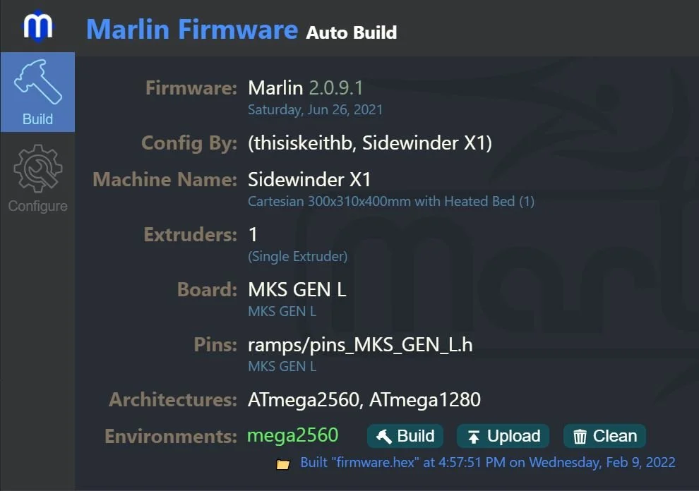
Build options for Sidewinder X1

During upload the touchscreen data cable has to be unplugged.

Finished Result
Overall I’m really happy with the finished result! It’s not quite as clean as the original ribbon cables, but it’s much cleaner than what I’d have to do before with the loose bypass wires.
I’m also really happy that the whole project ended up taking less than a month and only slightly more than the $40 alternative. It might not be worth the ~10 hrs of my time sourcing, designing, assembling but I got to try CircuitMaker and pick KiCAD back up so I’m not complaining (although I will complain about the other 10 hrs I spent fighting firmware demons but that was inevitable!!)