
Portable Power Supply Pt III: Testing
The project so far…
In my first blog for this project, I described the concept and design of a revised variant of an open source power supply enclosure. My design focused on adding safety features, improving ease of assembly, and reducing the form factor. In a shorter second blog post I detailed the process of assembling the unit.
However, I decided to make a large tradeoff in the design that warrants testing: the cooling system is massively downsized compared to the reference design.

Reference design (left) vs my revision (right)
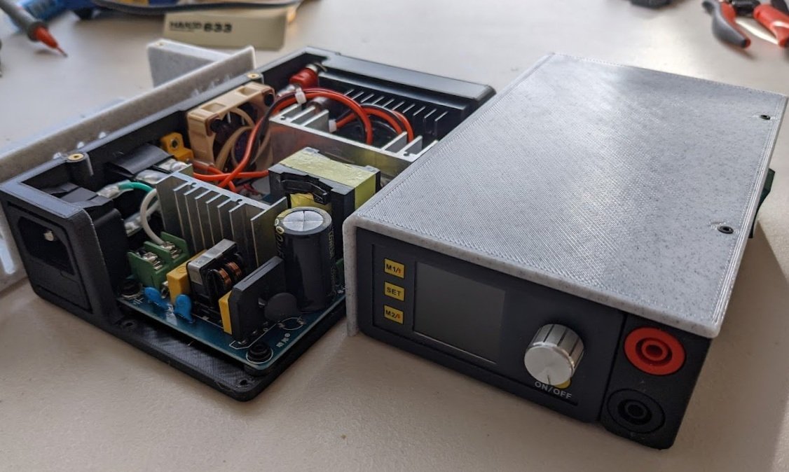
Partially assembled & fully assembled slim power supplies.
Generally when designing electronic systems you want to design components to supply more power than what they’re powering can consume. Generally it’s good to give them a factor of safety proportional to the severity of their failure condition or the cost/difficulty of replacement. In this case, due to limited options of appropriately sized AC-DC converters, that component is undersized, with the option to bypass it with a direct DC input. Fortunately, the maximum power consumption on the output module is adjustable, so it can be prevented from overloading and overheating the AC to DC converter.
Spreadsheet link to the documentation I generating including these charts.
Thermal Concerns
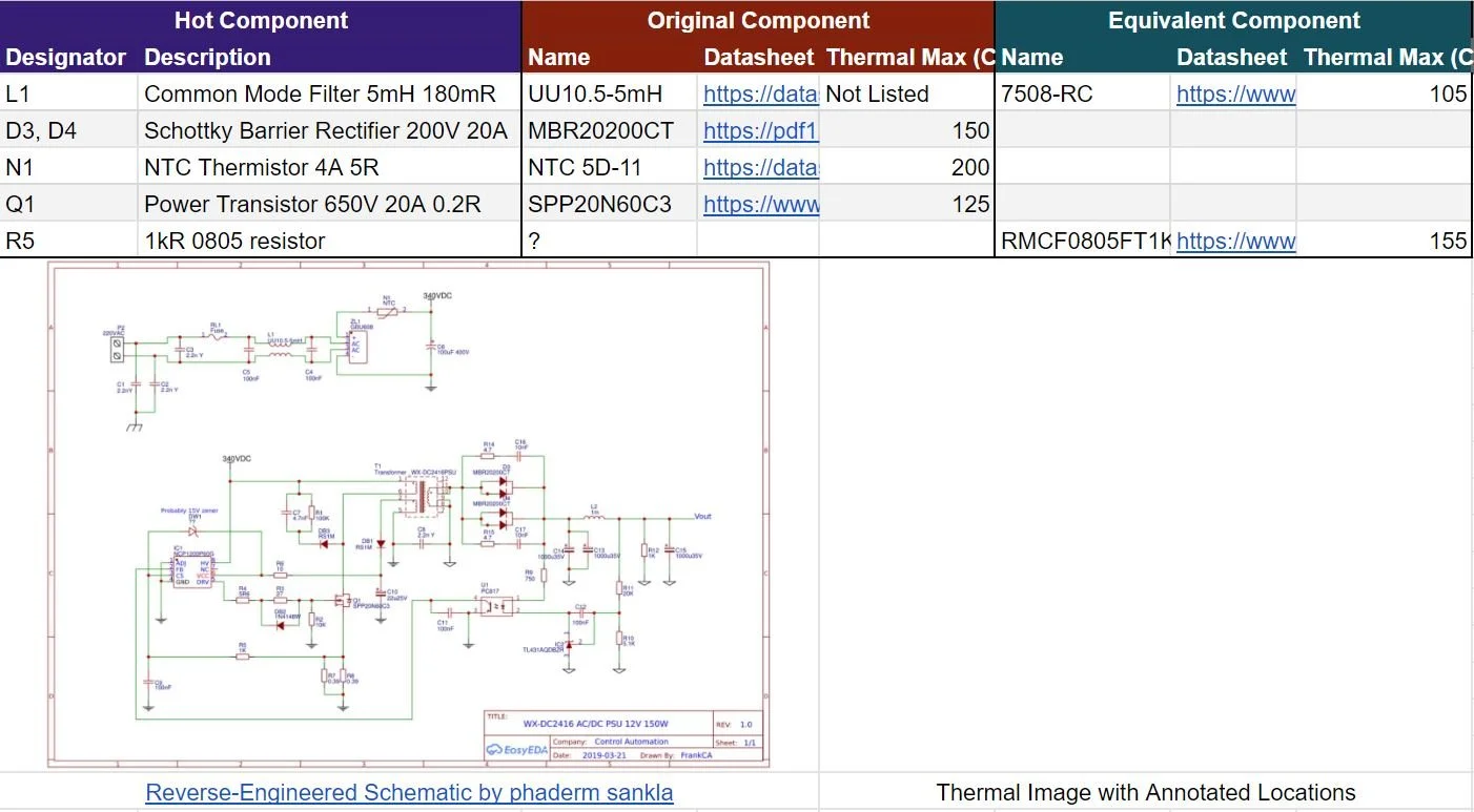
Based on a infrared image of the power supply at a 60W load for extended time, the chip markings, and a reverse-engineered schematic I found online, it was simple to identify the components that were generating the most heat. Cross referencing their datasheets (or a datasheet of the closest equivalent component I could find), I was able to find the maximum operating temperatures of all the thermally-limiting components. I documented this on my testing spreadsheet.
Performance concerns
There is also the possibility of the converter’s performance deteriorating at greater loads, so I decided to monitor the power-on and power-off conditions to detect potential voltage overshoot as well as using a multimeter to verify the output readings of the scope.
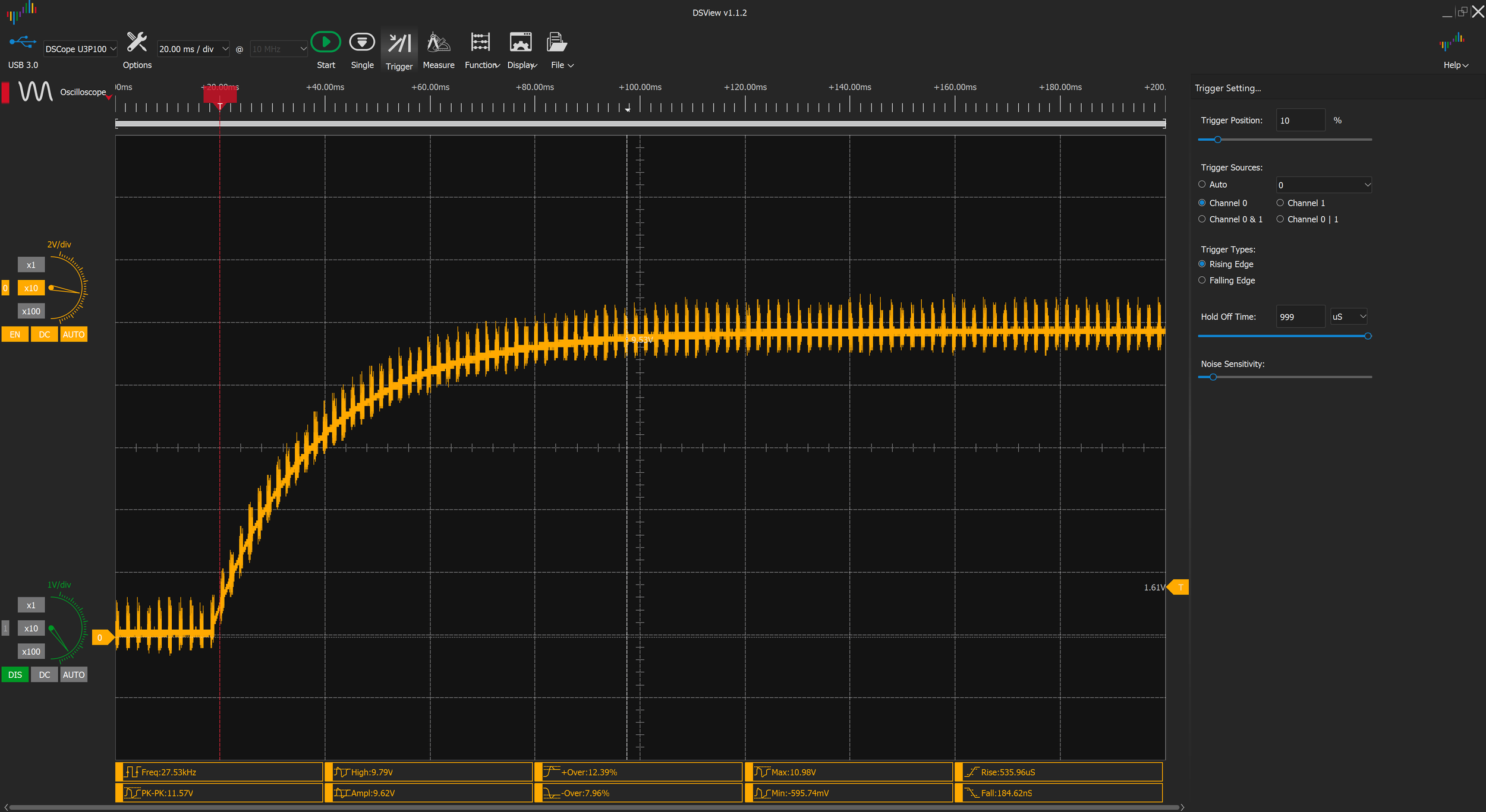
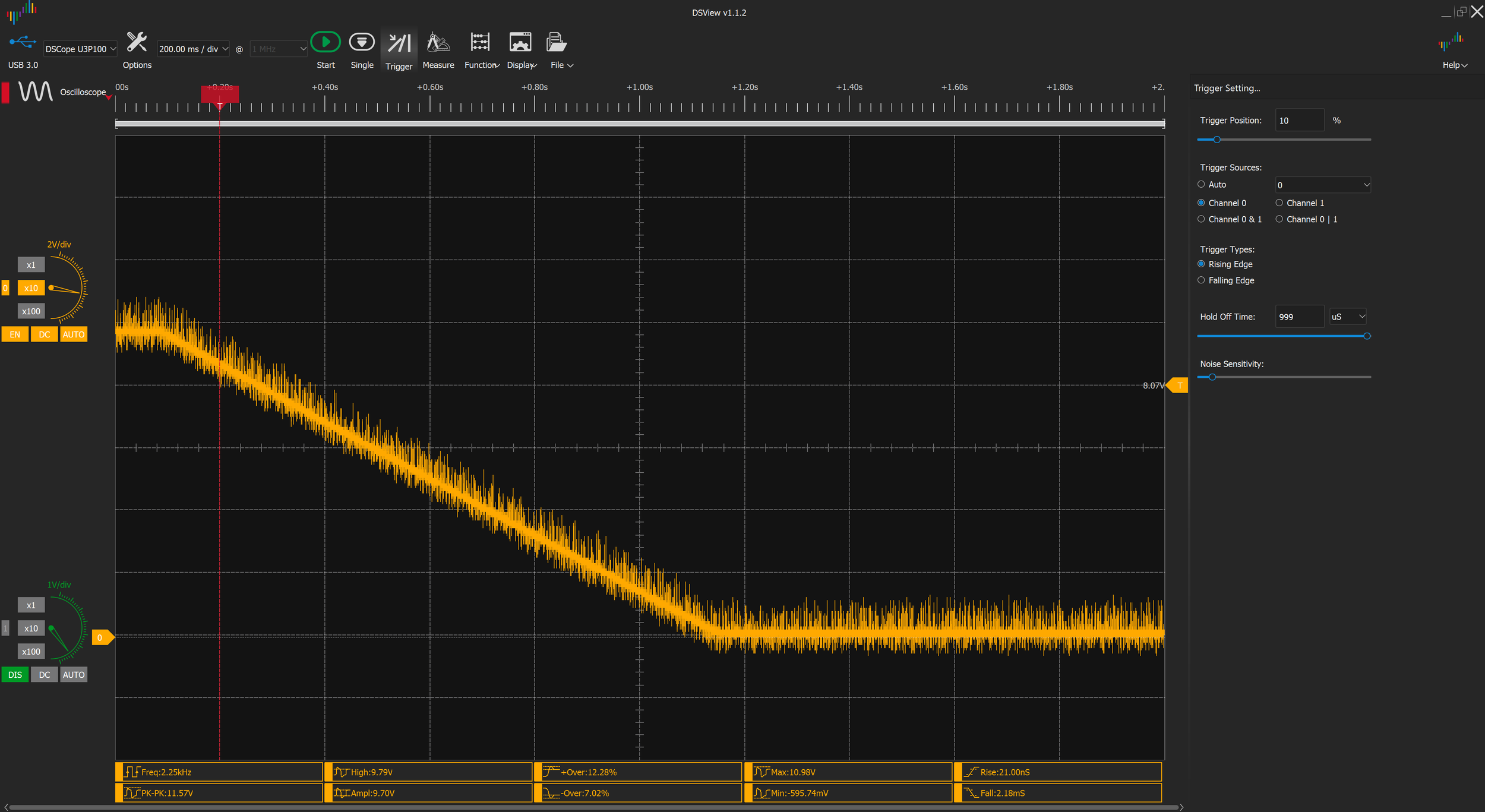
Testing Methodology
I wanted to be a bit thorough with this and be confident in my data, so I used this as an excuse to buy a Flir One Pro thermal camera and a Dscope U3P100 USB oscilloscope for my setup. I always prefer compact, portable products, as I’ll be moving soon, and both these fit that philosophy to a T! My setup (pictured right) consists of the power supply hooked up to a network of 4 resistors creating an overall load of 6.1 Ohms with a max power dissipation of 200W (although it gets really hot). To measure the AC input, I’m using a Kill-A-Watt AC Power meter (complete with power factor measurement), while the output is being measured by a BK Precision Digital multimeter in autoranging DC voltage mode and the USB oscilloscope mentioned earlier. The tests were performed with the power supply enclosure open at the top and later compared to readings of critical components through the case to ensure that forced convection wasn’t inferior to the open tests.
The testing methodology was as follows:
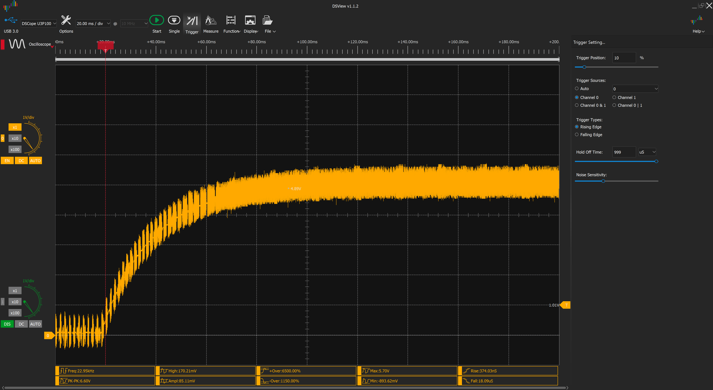
Set up oscilloscope to record rise condition, increase voltage, power on & save scope readout
Wait 5+ min, then take thermal and meter measurement, record file names
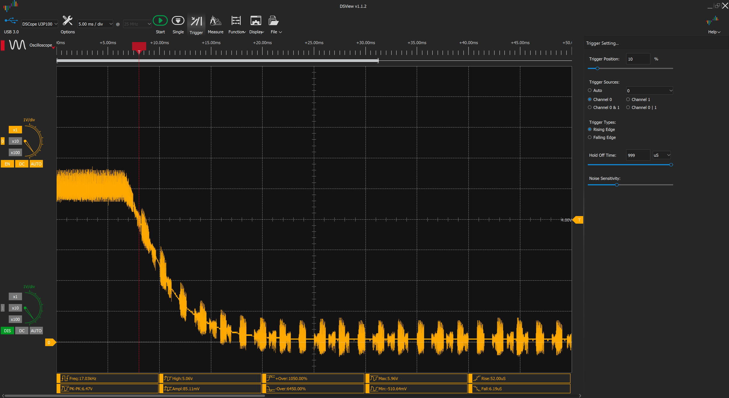
Set up oscilloscope to record fall condition, power off supply & save scope readout
Repeat until at max voltage or test becomes

A picture of the testing setup. From left to right: USB oscilloscope, Kill-A-Watt USB power meter, Phone with attached thermal capture module, Power supply, Multimeter (used as DC autoranging voltmeter), Load resistors and cooling fan, and Camera on gorillapod to capture meter measurements.
Electrical Performance
Overall I’m really happy with the overall electrical performance. Rise Times were consistant across loaded and unloaded conditions, while fall times scaled linearly with voltage with no load and stayed constant with load. The voltage output errors are also favorable. Scope outputs for all 20 load scenarios is captured on the testing spreadsheet.
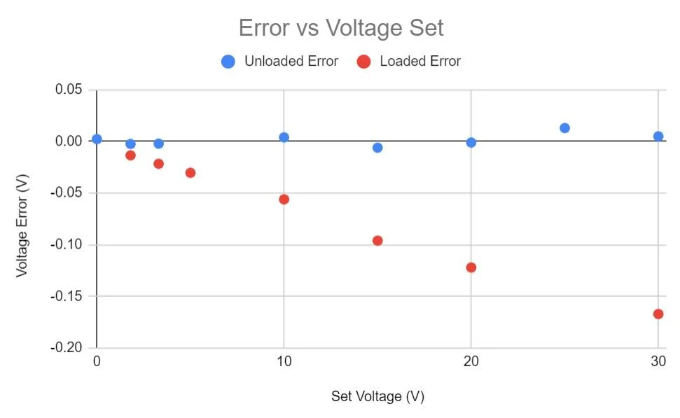
Errors are consistent and low with no error and linearly rise under max load. Likely source for this is the resistance of the test leads.
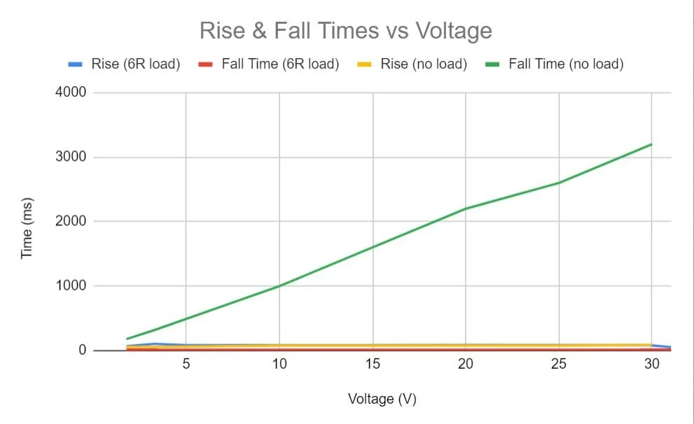
Fall times when unloaded take forever, but otherwise all rises / falls are consistant and take < 90ms.
Thermal and Efficiency Results
Overall thermal results with passive convective cooling were interesting. Overall most components scaled around what the datasheet suggested except for the AC common mode filter, which heated scaling with the square of power draw. I’m not sure what causes this, but the steep temperature explosion makes selection of a power limit very easy. The testing spreadsheet has thermal images for every load case.

No load temperature at Max voltage

Hotspots During 31V, 158W test. The 155.4C component is the AC filter.
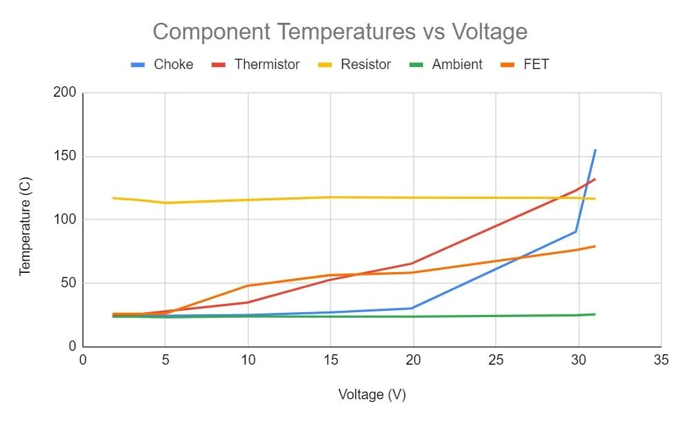
Graph of component temperatures under 6.1 Ohm load. Thermistor temperature scales well with the power output, but the AC filter or ‘choke’ scales near the square of power, causing an absurd overtemperature condition around 150W.
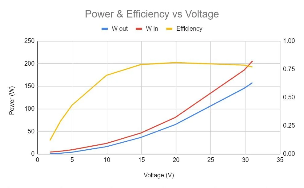
The constant 3W draw of the system (composed of indicator LEDs, fan power draw, and parasitic resistances) affects efficiency at low voltages heavily but doesn’t scale at higher values. The
Enclosure Thermal Validation
To confirm that the fan was doing an adequate job of ventilating the unit when fully enclosed, I performed the same 31V 6.1Ohm 158W test on an enclosed unit as I did in the final round of incremental testing. The thermistor visible through the cooling vent reads a lower temperature after reaching steady state, indicating better cooling performance. This isn’t as thorough by any means but is a good indicator that the active-convection enclosed system and the passive-convection open system perform similarly. I also did a secondary test with a thermocouple wedged underneath the AC common mode filter (the hottest component) at a safer 30V and it didn’t exceed it’s rated temperature when enclosed or unenclosed.

31V 158W load viewed through sidepanel of enclosed unit

31V 158W load viewed from top of open unit
Final Power Limits
Due to thermal limitations it makes sense to set a upper supply overpower limit of 150W on the default profile. We can keep the other profiles maxed so they can be switched to with a single button hold of the M1 or M2 buttons when moving to the DC bypass. This setting will be reverted to default on power cycle.

Initial parameters with supply overvoltage, overpower maxed.

Final adjusted parameters, supply overvoltage set at 32V and overpower protection set at 150W
Design Files & BOM
The BOM is available on my documentation spreadsheet for the project.
CAD files (solidworks, step, and stl) are available on github. They’re licensed under GPL to promote more hardware projects to be open source :)