
Carbon Fiber Molding Exploration
I haven’t been doing so much mold design recently, and the combination of an interesting video and a reddit post spurred me to some random CAD.
Compression molding industrially means applying a shot of generally preheated material to a heated mold and closing it using extreme pressure, allowing excess material to flash or otherwise . This allows rubber to be vulcanized in-mold, or advanced composites to be molded at scale.
This video (on right) from Easy Composites LTD details how to use a modification of this technique to create forged carbon composites in a DIY environment. Forged carbon is a really cool material that’s typically impossible to DIY since it requires high pressures and precision molds to remove the voids from its epoxy-impregnated loose carbon fibers into a single material. Forged carbon isn’t as strong as a traditional vacuum-bag layup for large parts, as the individual fibers are much shorter and aren’t interwoven, but it is much more isotropic and using compression molding it is able to achieve high-resolution features on small parts. It has relatively comparable yield strength to Aluminum while being half the weight and considerably stiffer.
I’ve been fiddling with Rubik’s cubes a bit lately, and a moment of serendipity struck when I saw the reddit post at right, which asked if it’s possible to making a Rubik’s cube out of carbon fiber instead of plastic, and I decided to play around with the idea in CAD… sohere we are.
The inspirational video tutorializing forged carbon compression molds

Reddit post that spurred me to start a feasibility study

Speedcube internal mechanism: center, edge and corner pieces slide together despite not being attached.
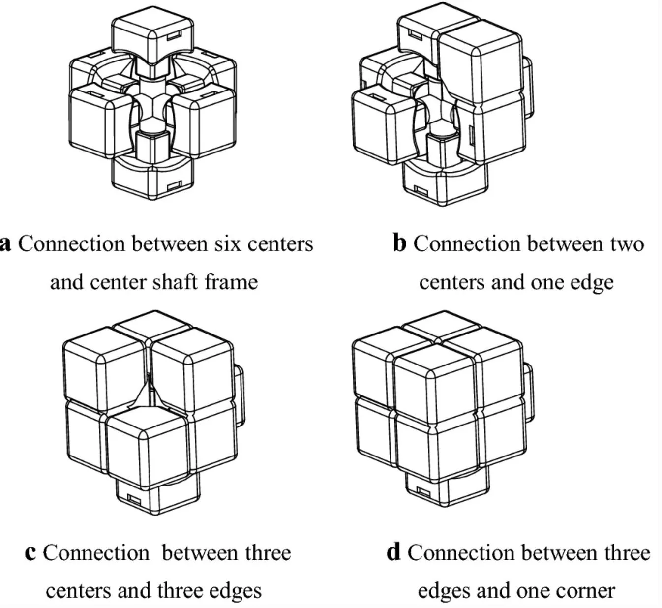
Diagram of mechanism assembly from a paper on rubik’s cube mechanisms by The Chinese Journal of Mechanical Engineering

Speedcube design allows automatic correction of angles, aka ‘corner-cutting’

Doing 2 7-move sequences back-to back in 4 seconds
How Speedcubes Work
Speedcubes are off-brand Rubik’s cube that employ advanced spring mechanisms to give the cube a little flex which allow top solvers to turn the cube over 10 times per second in alternating directions (although I max out at about 4 right now)
The overall mechanism works as so:
Center pieces rotate on screws attached to the central core, and are pulled towards said core with springs
Edge pieces extend underneath the the two center pieces they’re between
Corner pieces extend underneath the nearest 3 centers and 3 edges
Piece Design / Reverse Engineering
Overall to make a carbon-fiber Rubik’s cube is a total fool’s endeavor, but it’s a fun thought-exercise and design challenge. I used the RS3M as a reference design, since it’s the simpler of my who cubes
A vacuum bagged wet layup at this scale would be a nightmare to postprocess and be really inconsistent, so I think a forged carbon compression molded version is the only way to go for the internal mechanism components. Running a slight resin surplus you can get really good resolution with forged parts, but they're not well suited for the thin flat faces of the cube, which would definitely prefer a wet layup or prepreg. Assuming you can get away with forged for all of it, you'd probably need 2 unique 3-part compression molds (edge and corner inner faces), 4x 2-part molds (outer faces & center inside), and an existing core or machined aluminum core since CF doesn't hold threads well, and aligning 6 insertion nuts sounds painful.
Reverse engineering the pieces from the RS3M was comparatively simple. I used a pair of calipers and some orthogonal reference photos. The reference design uses a minimum thickness of 2mm in the internals and 1mm walls on the hollow walls which I kept here.
Where I got stuck was on closing the pieces... carbon fiber can't make flextures or press fits at these scales due to comparitive brittleness & non-isotropic nature, but making something this expensive that's just epoxied closed would be a travesty. My initial thought was using a steel dowel to run a tiny machine screw hole through the internal part and epoxying a nut in but that would be super heavy. The design I settled on was a carbon fiber press-fit pin cut from 5mm tube stock with embedded epoxied magnets. Speedcubes often use magnets to help the cube ‘click’ into a cube-shape, and having the magnets be interchangeable or adjustable is a consistent premium feature. Embedding the magnet in this pin would allow it to be exchanged if necessary.

Edge piece and center piece parts for WR M 2021 (top) and the cheaper and simpler RS3M 2020 (bottom).
Finished redesigned RS3M edge piece CAD. It maintains the external dimensions while redesigning the internals to fit the manufacturing method.
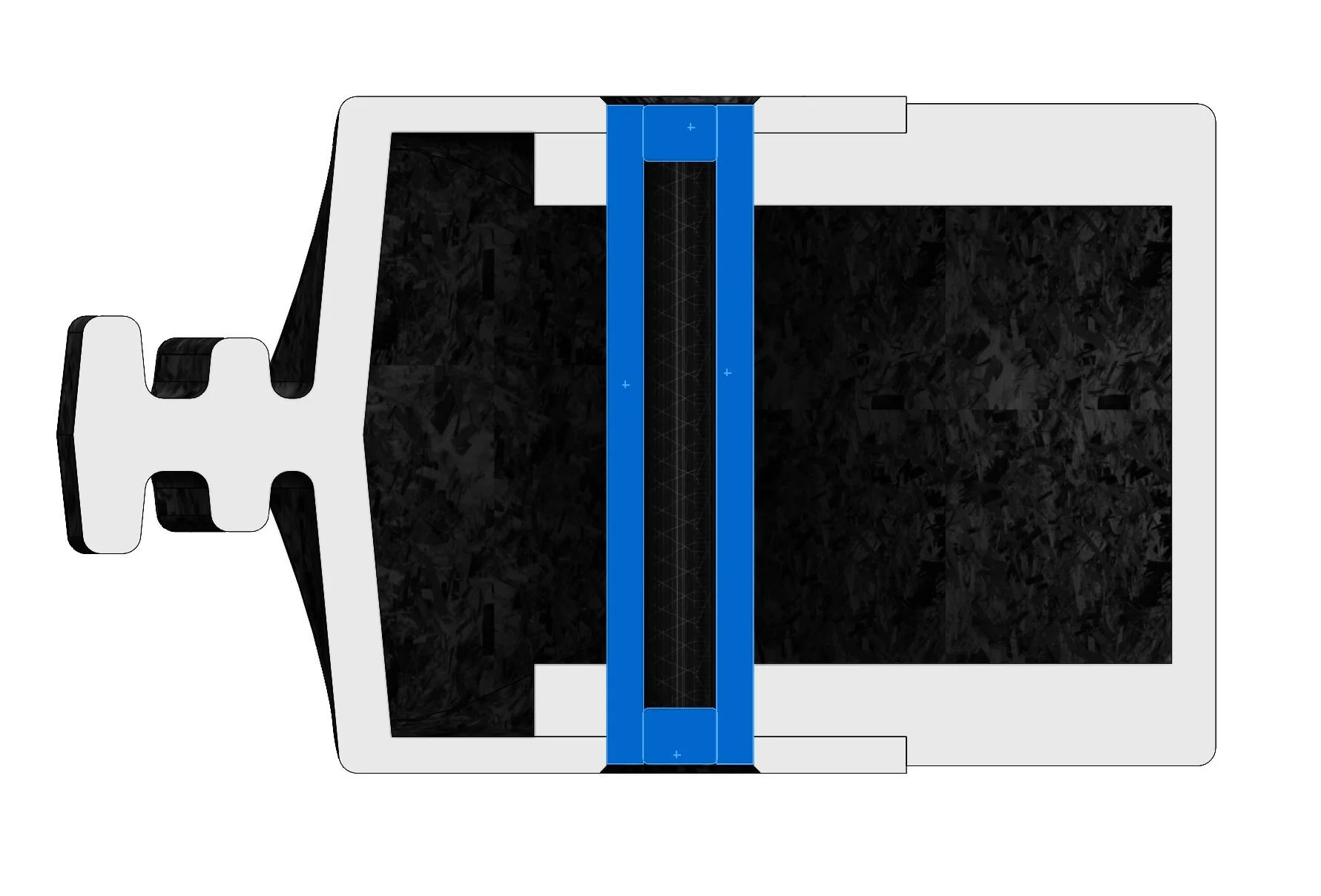
Cross Section of assembled edge piece. Hidden mechanical part with all sliding & aligning geometry( left) is held to externally visibe edge (right) with assembly pin(highlighted blue). The assembly pin additionally contains the magnets used for automatic alignment.
Mold Design
Despite being a very powerful tool for making smaller, more feature-dense carbon-fiber parts, DIY compression molding has a lot of drawbacks that have to be designed around.
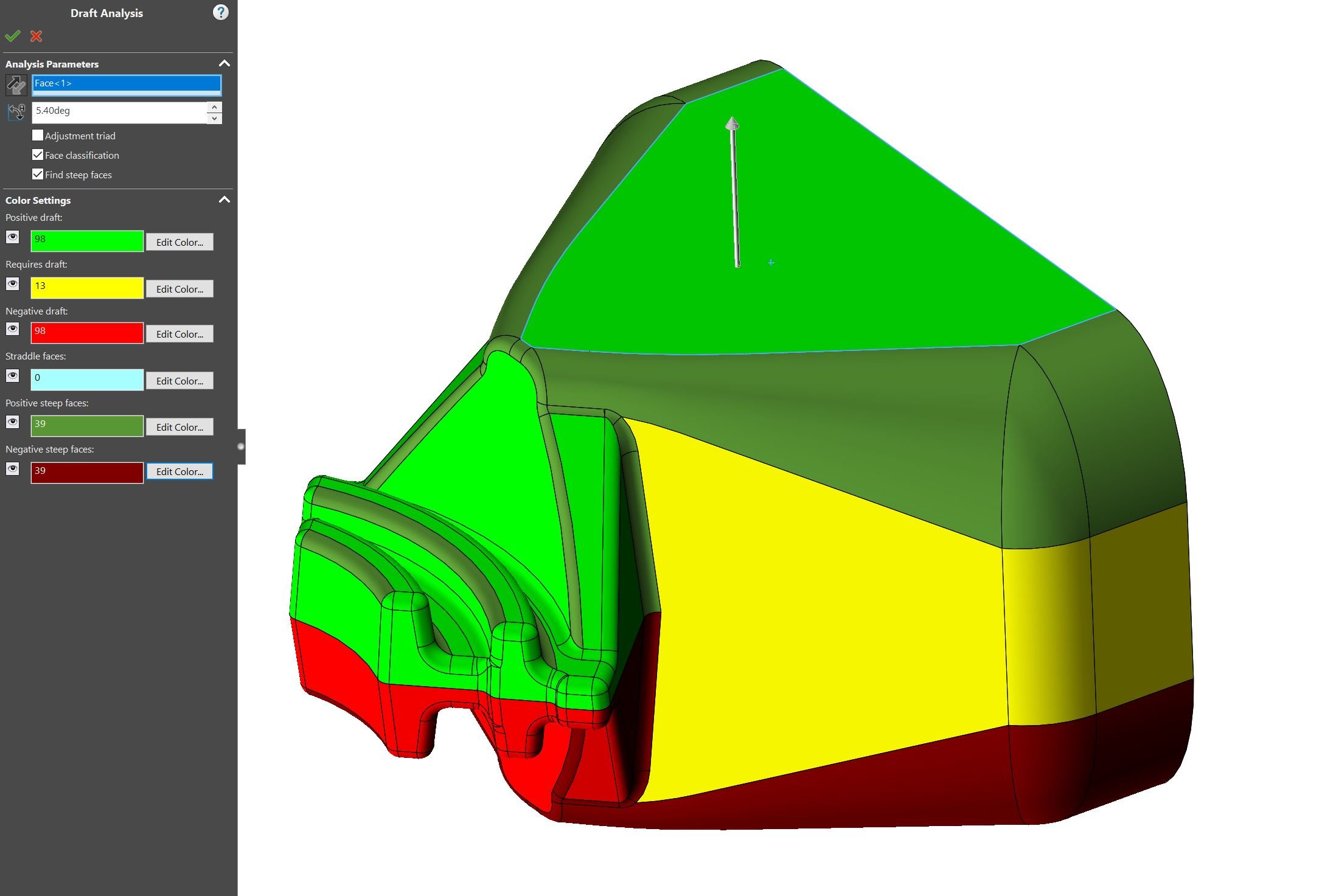
Firstly, standard moldmaking techniques like drafting, chamfering, and filleting must be used to make a machinable. Adding these features was pretty simple, and I adjusted the part to be machinable with a 1mm 5.4 degree ball nose carving mill and a 3mm endmill for the vertical sides.
Secondly, and more importantly: since the volume of the compressed material is due to variable material, loading, and clamping pressure being slightly variable, features in the compression direction have to be non-dimensional and capable. That means it’s impossible to create complex features to terminate the part in the compression direction, since the part has to terminate parallel to the compression direction.
Due to these limitations, several features had to be handled in postprocessing.
Molded Part Postprocessing
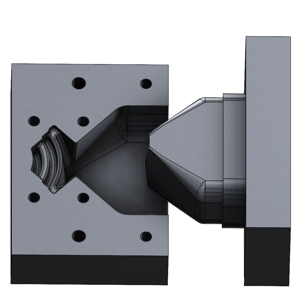
Since compression molding using the major undercut can’t accurately recreate the features near the undercut used as the compression face. In particular the hole for the magnet / assembly pin and the curved edge of the part. The postprocessing jig clamps around the part and provides a bushing to align the drilled hole and a hardened steel surface to constrain sanding to the intended shape of the part.
In addition to correcting the part’s shape, in order to give a smooth sliding surface the external faces would have to be coated in a durable 2-part clearcoat and polished to a mirror finish.

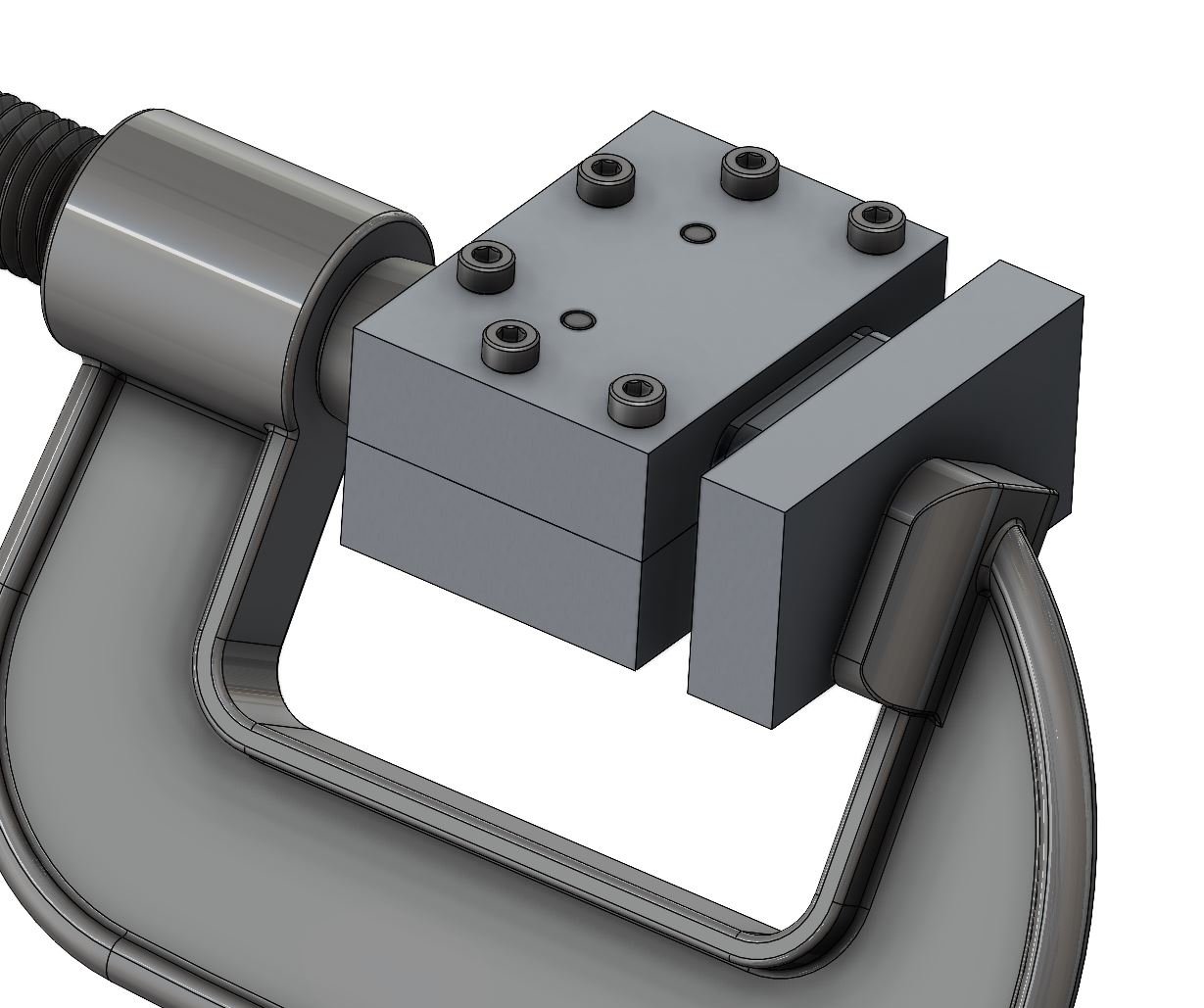
Postprocessing jig locked around raw molded part
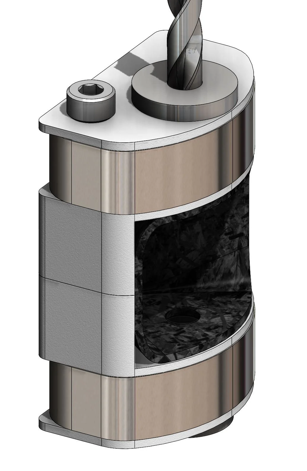
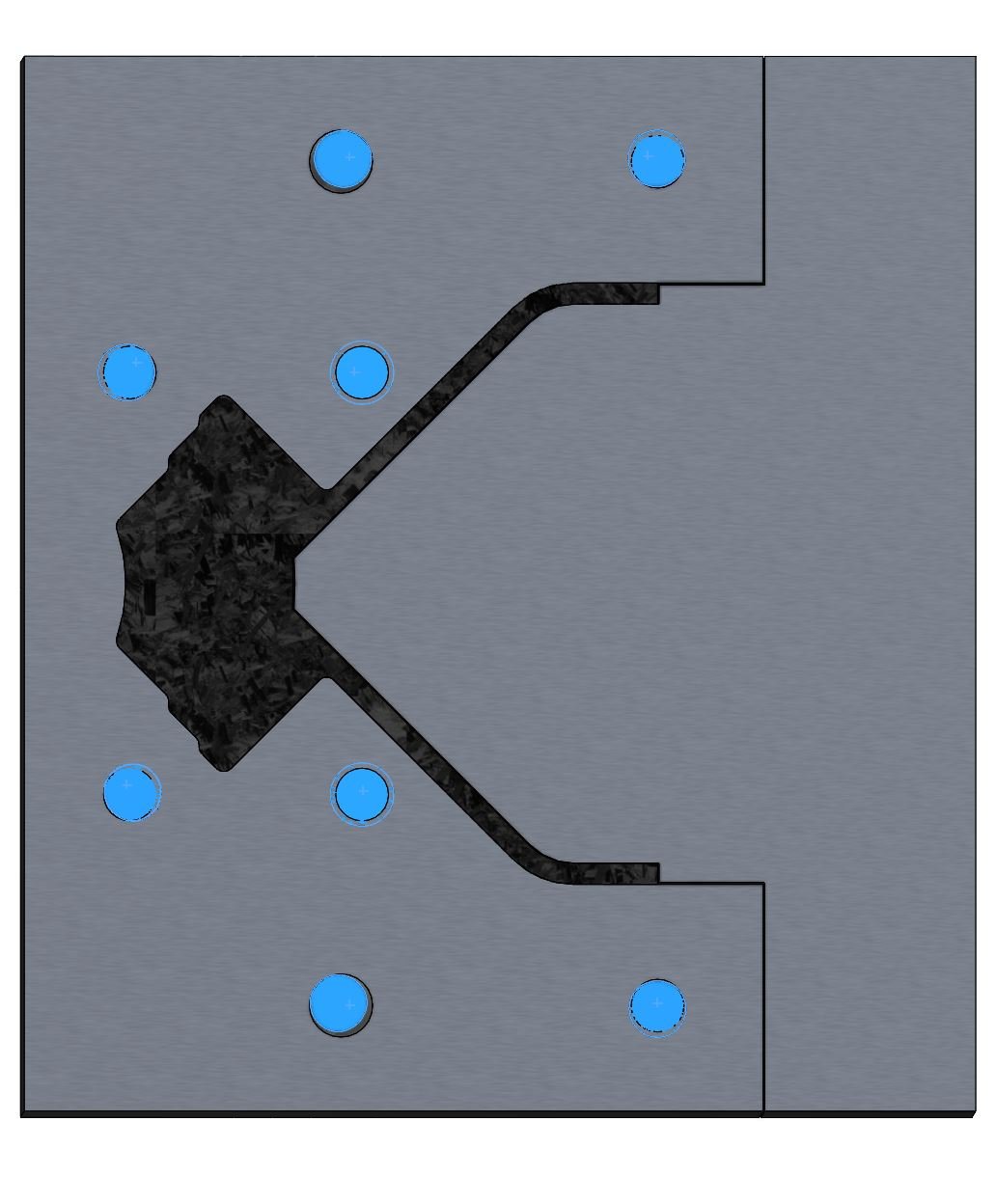
Jig after sanding and drilling
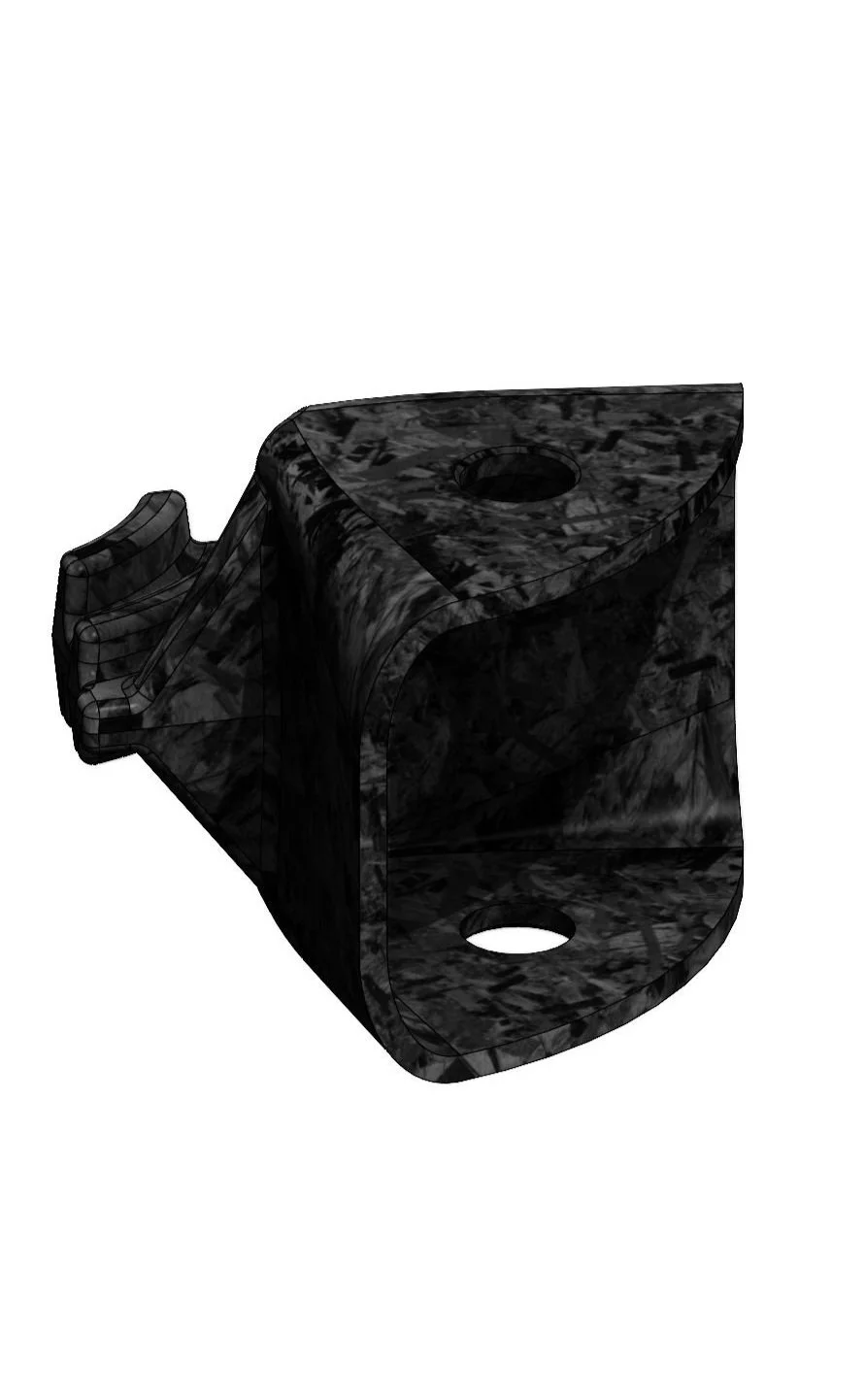
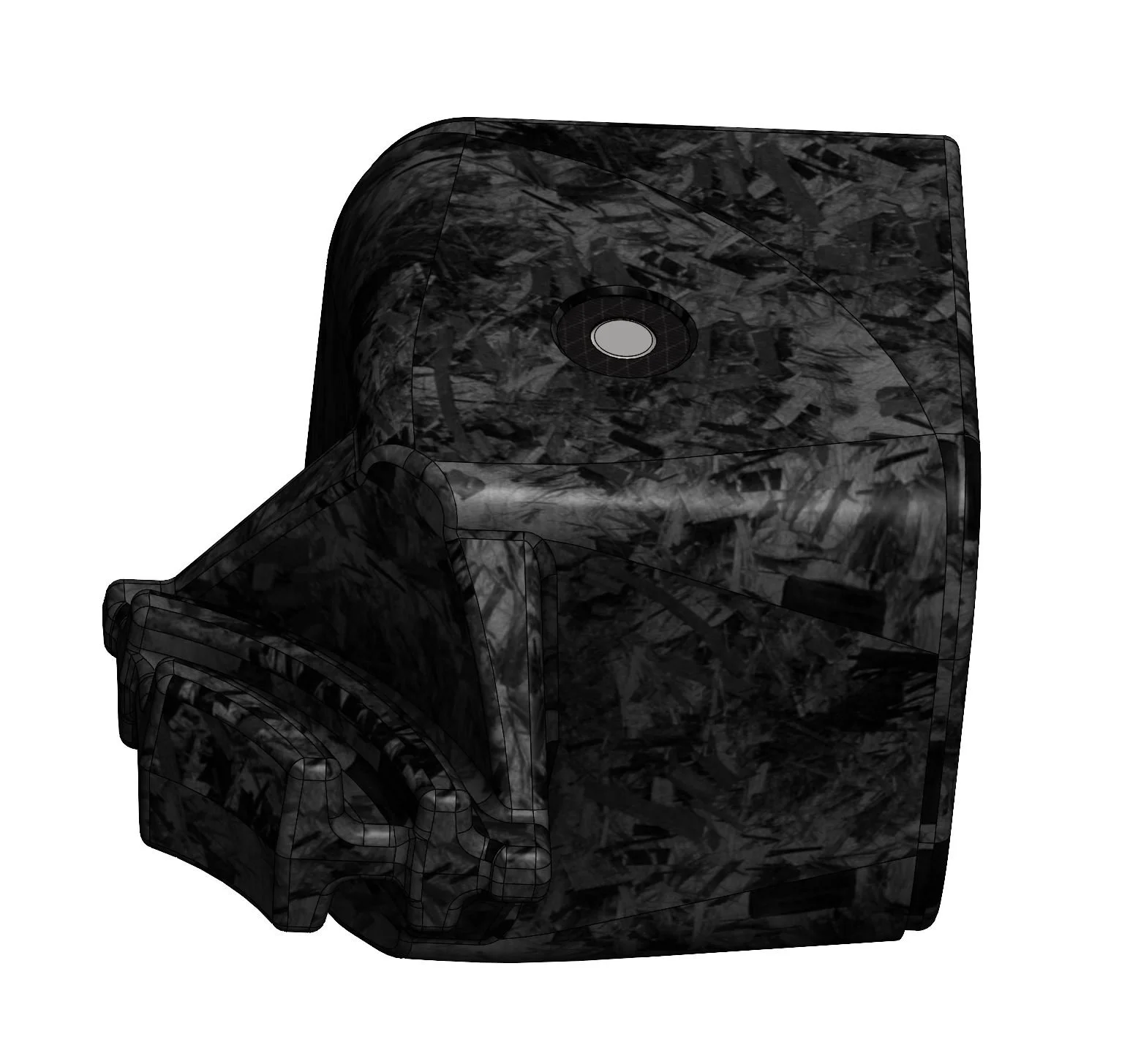
Fully postprocessed part
Conclusion
In the end although the cube would be exceptionally pretty, it would still be pretty heavy (since density of carbon fiber is higher than ABS and you wouldn't be able to go thinner), with performance comparable to a budget speedcube if done perfectly. Designing one set of over six necessary mold & postprocessing jigs took around 5 hrs. Machining each would require $100 of aluminum stock, hardware, drills, shims, bushing, and steel, several hours of machine time, and many hours of molding & postprocessing, all for something that’s likely to fail due to small feature size or underperform due to surface finish. If you really wanted to make a carbon-fiber speedcube, take an existing stickerless version and remake the piece caps instead: the internals only get more expensive and heavier in carbon fiber.
Overall this is a terrible idea that was fun to investigate, but I’d never pursue any further. Doing some speedcube design (maybe a novel puzzle), some CNC machining (maybe an aluminum product enclosure), and forged carbon compression-molding (maybe some bike parts or a phone case) indiviually sound like a blast but this combination is absolutely doomed to the CAD archive folder. If anybody’s masochistic enough to continue this, message me and I’ll add you to a private github repo.