
Ring Spinner Combat Robot v1&2
Back in college I realized I wouldn’t have access to a CNC and a high strength 3D printer and wanted to use the opportunity to get into combat robots! Combat robots like seen had fascinated me ever since I’d seen the OG Comedy Central Battlebots in middle school.

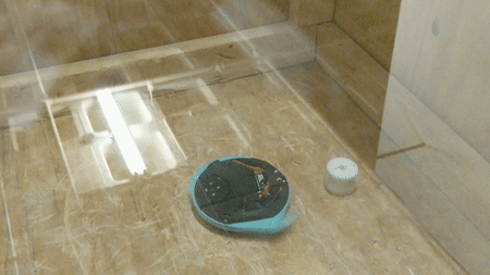
Example 250 lb full-body spinner, ‘captain shredderator’. Note the full armor and the rotation shaft in the middle of the top.

Example 250 lb ring spinner, ‘ring master’. Note the wheels visible on the top side.
Robot Overview
My personal favorite weapon design in the sport has always been the full body spinner, the simplicity of the weapon and armor combined into a monolithic weapon-armor with potential for completely unmatched kinetic energy. And if you’ve read any of the rest of my blogs you probably know I deeply enjoy pointlessly optimized things: the super long, stiff sword, the huge sledgehammer, firespinning props with bearings… you get the point. However there was a variant on the full body spinner called the ring spinner, which takes all the benefits of the full body spinner, while throwing its relative simplicity in the dumpster in favor of solving it’s biggest weakness, invertibility. During a match, it’s highly likely that the bot will flip over due to an impact, which is a huge problem for full body spinners, which generally have difficulty flipping over and can’t drive inverted. Ring spinners solve this by having only the outside sim of the robot spinning, while the wheels are free to poke out both the top and bottom of the bot.
The extremely elegant approach to weapon & armor of the ring spinner really appeals to me, while the added complexity seemed like a fun challenge, so I decided to go for it and make my own 3 pound ring spinner!
I’ll go into is much detail here as possible on the overall design and execution of this process, but I won’t go into much of the technical details, like weight estimation and component selection.
Constraints & Design
Everything has to be designed with strong knowledge of the constraints involved: and besides the rules constraints of the class: the 3 lb weight limit and accessible power switch, the main constraints I considered were in manufacturing. Some of the main constraints I came up with were:
Use as many COTS components as possible
3D prints limited to 132mm wide
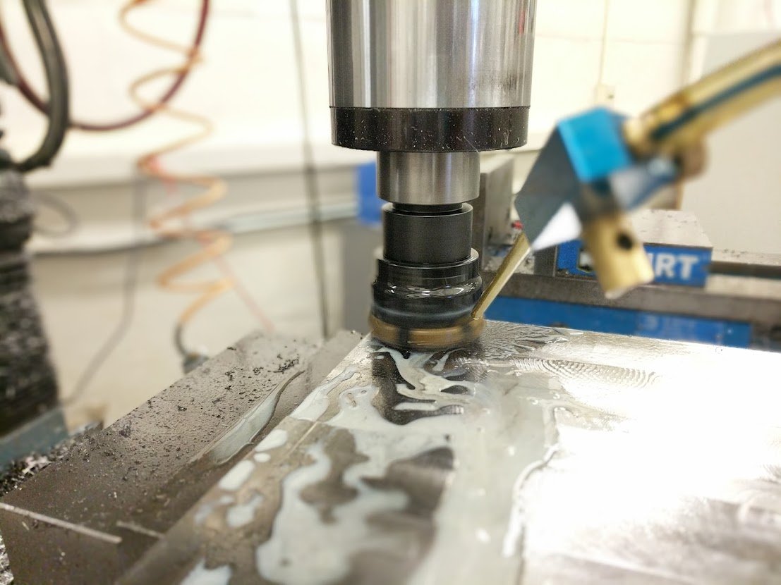
Weapon material manufacturable on CNC mill with HSS end mills (poor student yay) while not requiring heat treatment
Highly resistant to impacts (no impact forces directly translatable to motors or electronics)
Capable of driving inverted
2s spinup to 90J, at least 120J of energy at full speed (runamok guidelines)
Battery to last ~2 min of continuous driving
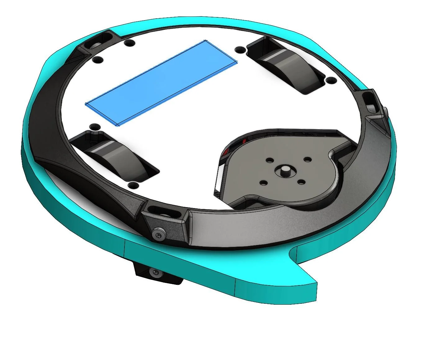
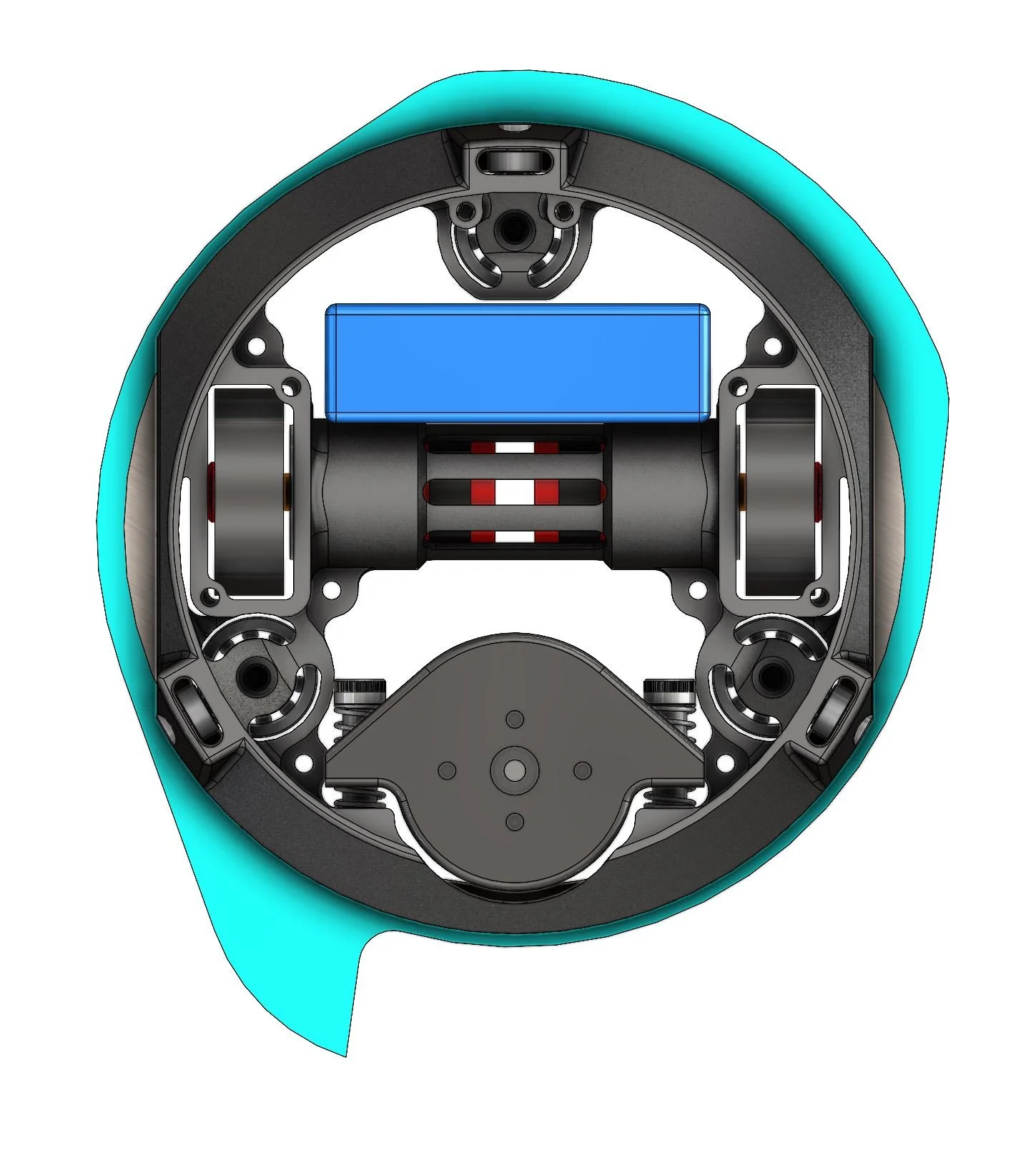
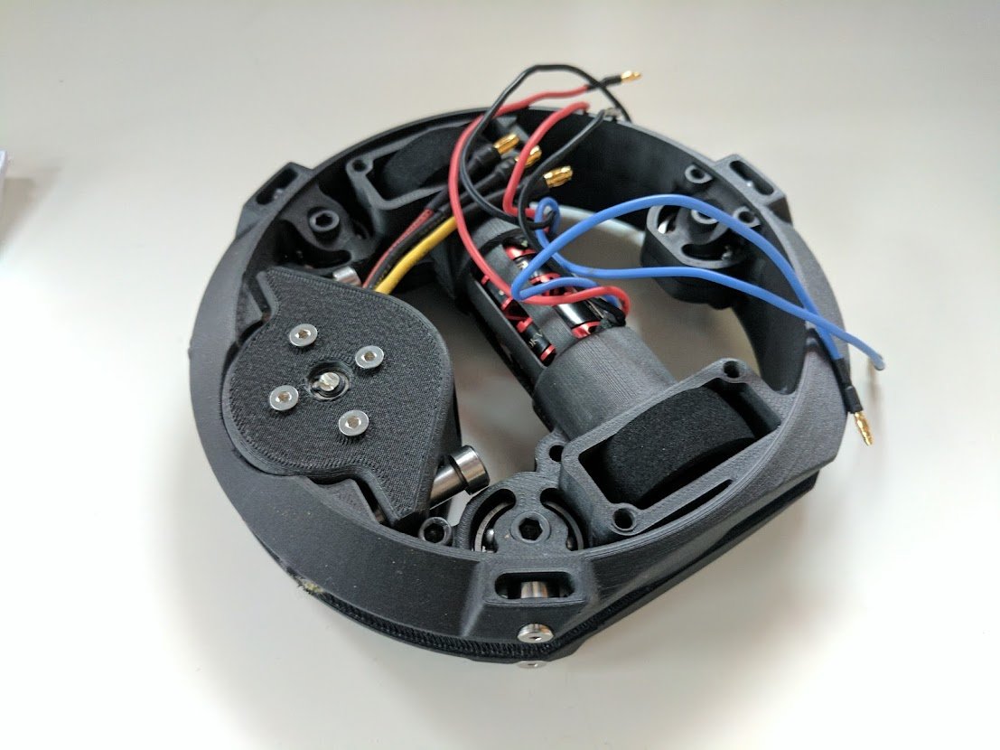
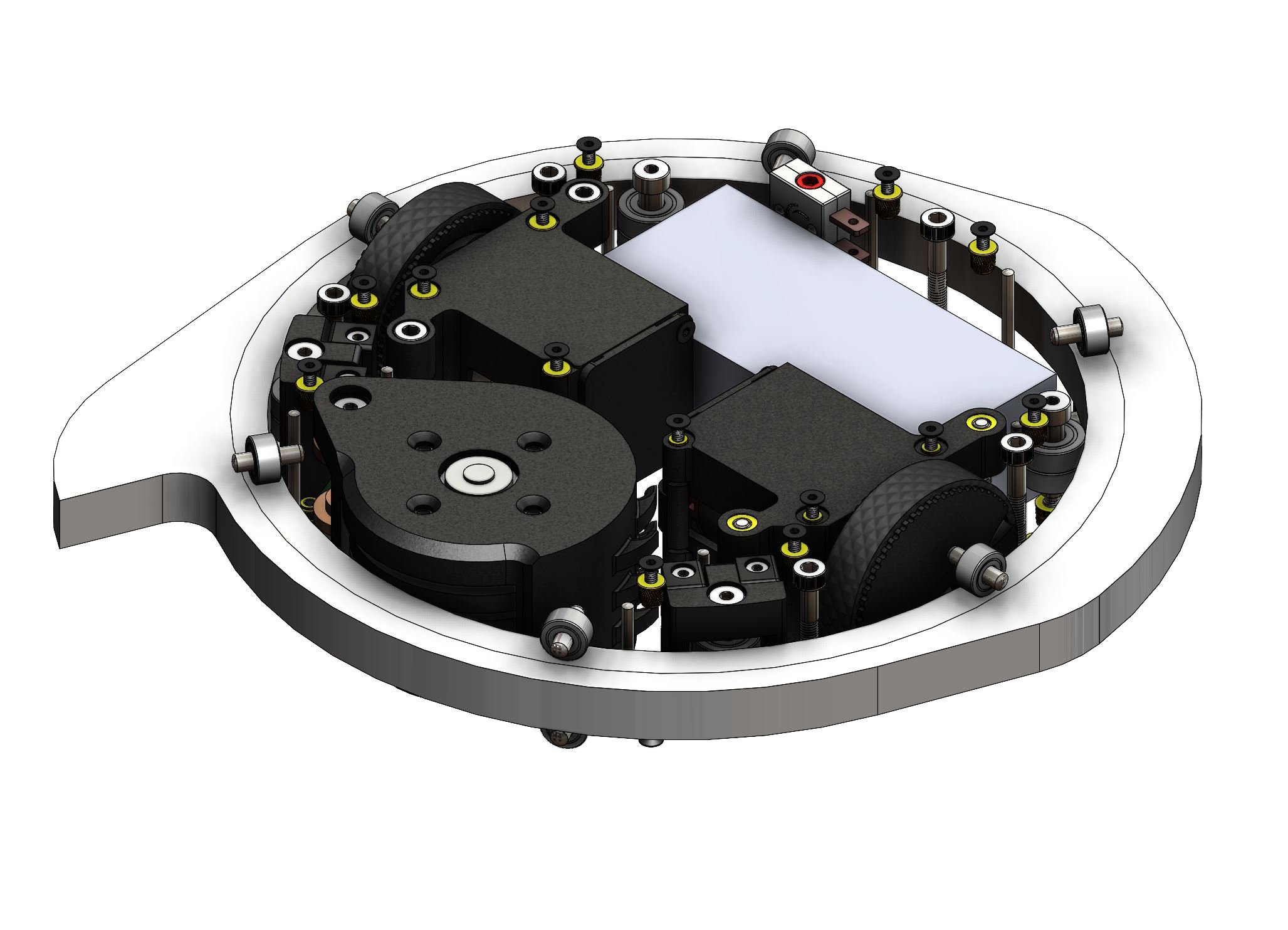
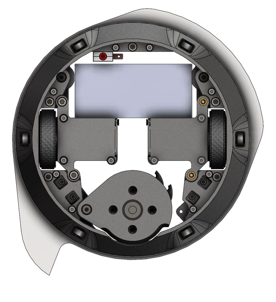
Due to the width constraint of the 3D printer, I had to design the robot as compact as possible, as the width of the 3D print effectively set the inner diameter of the disk. Since the wheels had to be taller than the robot and space was at a premium, the robot therefore had to be as dense as possible. Working from these height and diameter constraints it was pretty easy to size and lay out most of the components.
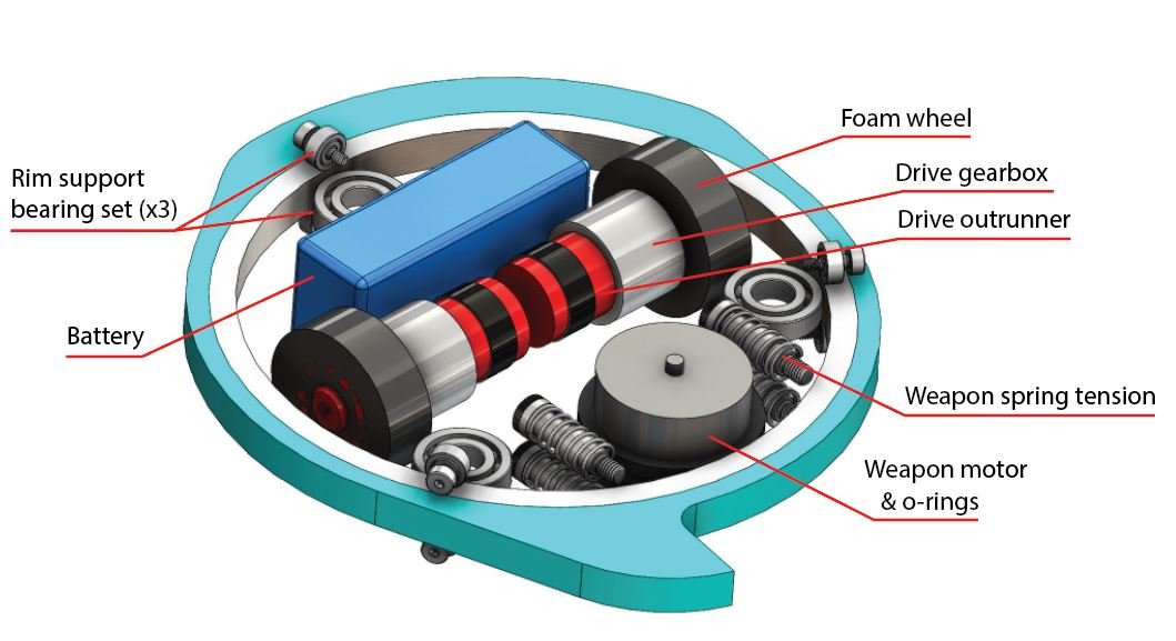
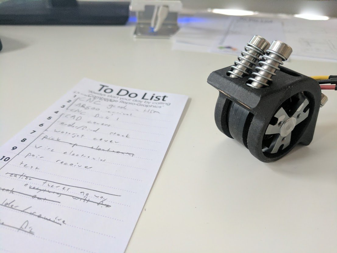
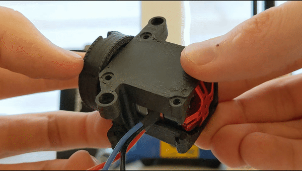
The drive system came as a recommendation from the knowledgable Alex Hattori: mashing together the gearbox of a standard DC gearmotor with a tiny brushless outrunner gives a smaller, more powerful drivetrain, with the output shaft pre-sized for durable foam wheels.
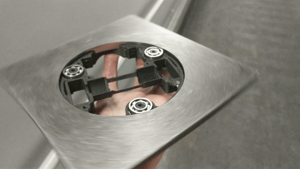
The weapon rim is supported by 3 sets of bearings and driven by a 380W outrunner contacting the rim through square-profile o-rings. The rubber contact of the o-rings protects the outrunner bell from sharp decelerations while a system of four springs and shoulder bolts allows the weapon motor to deflect radially away from the rim in case of hard impacts.
Design Failings
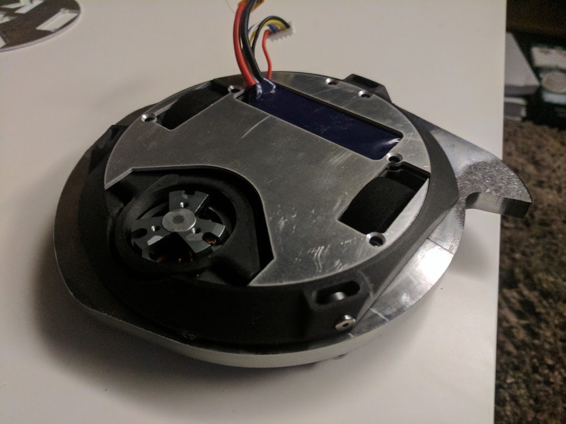
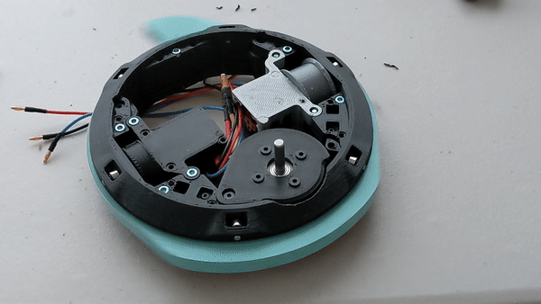
Despite my best attemps, I struggled with the volumetric constraint throughout the design. Ultimately, the battery didn’t have vertical space for any armor, and there wasn’t much room for electronics.
Machining, Assembly, & Testing
Ultimately I decided to go through with manufacturing with the goal of making something functional, even if flawed.
v1 Issues Overview
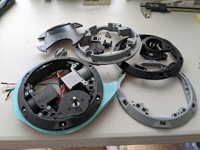
Assembly was tedious and troublesome due to the fact that in order to change the motors, weapon blade, or bearings, the robot has to be essentially fully dissassembled
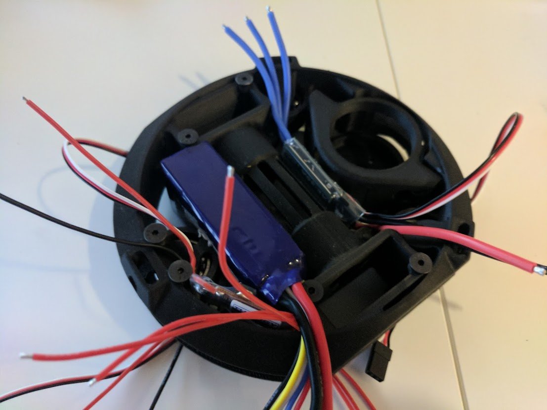
There isn’t enough internal space for the electronics, this meant I had to dremel the inside and even with that the top/bottom plates bowed quickly
The battery is completely exposed on both the top and bottom of the robot It’s a huge and annoying weakspot, even without an combatant
The four pins in the weapon motor assembly easily jammed: high aspect ratio cantilevers mounted in soft materials are always a terrible idea
The main bearings were held by 3D prints, meaning that even though the bearings were capable of ~100g impacts, they were sitting on hollow plastic pins, these needed to be replaced by shoulder bolts
The drive motors were such a tight fit in the shell that there was only 1mm of clearance between the 2 outrunner rotors, which could rotate at different speeds or impacts
The weapon rim was unbalanced which caused huge vibrations at speed
Overall, the main frame needed a massive redesign, not only to make it more compact, but also more modular to make it repairable. Unfortunately I lost access to the Markforged printer, and the loss of the ability to reprint shelved the project indefinitely.
Overall Thoughts on v1
Despite the number of issues in DFA that kept the robot from competing, I was really happy with the individual systems’ functionality. Driving around with the brushless drivemotors was snappy and fun, and the weapon was absolutely terrifying for its diminuitive size. At full speed the rim was capable of storing a mind-boggling 500J, over 4 times the recommended baseline given by the combat robot Q&A. For a sense of scale 1000J is the amount of energy in a major league baseball hit, so this robot hits about as hard as I would with a bat!
However, I already knew this was a super ambitious first combat robot and I wasn’t too broken up by its design failings: I learned a TON and had loads of fun.
Version 2!!!
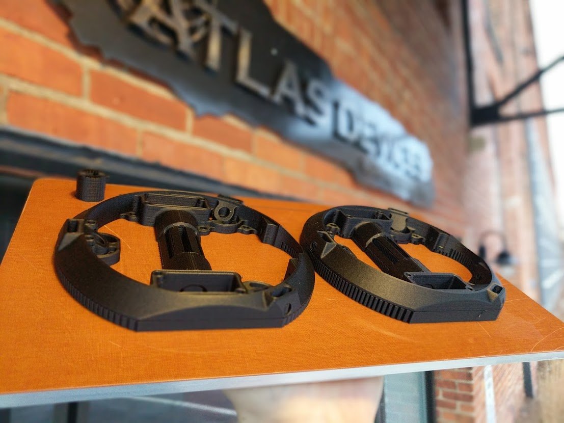
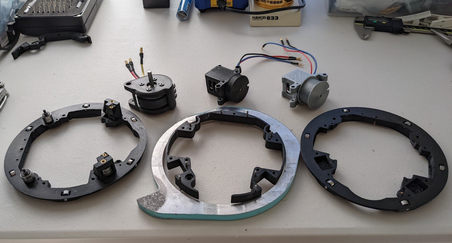
Fast forward to 2021: I’d completely forgotten about this project, but during a move rediscovered the robots corpse: stripped of battery and motors but with the rim still in perfect condition. With the realization that Battlebots competitions were reopening from COVID I decided to make a new version. I upgraded my personal 3D printer to print chopped carbon fiber nylon and set to work designing.
Changes from v1
Overall the design goals were quite similar before as I intended this to be a minor revision focusing on space optimization and modularity. To address each of the v1 issues as followed
Assembly issues -> modular system w/ independent drive motor modules & more modular weapon frame
Space constraints -> 4 sets of 2 double stacked weapon support bearings instead of 3 large bearings takes less space
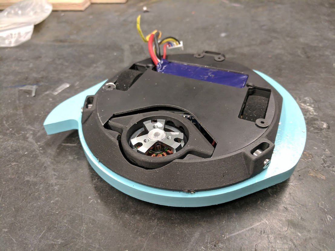
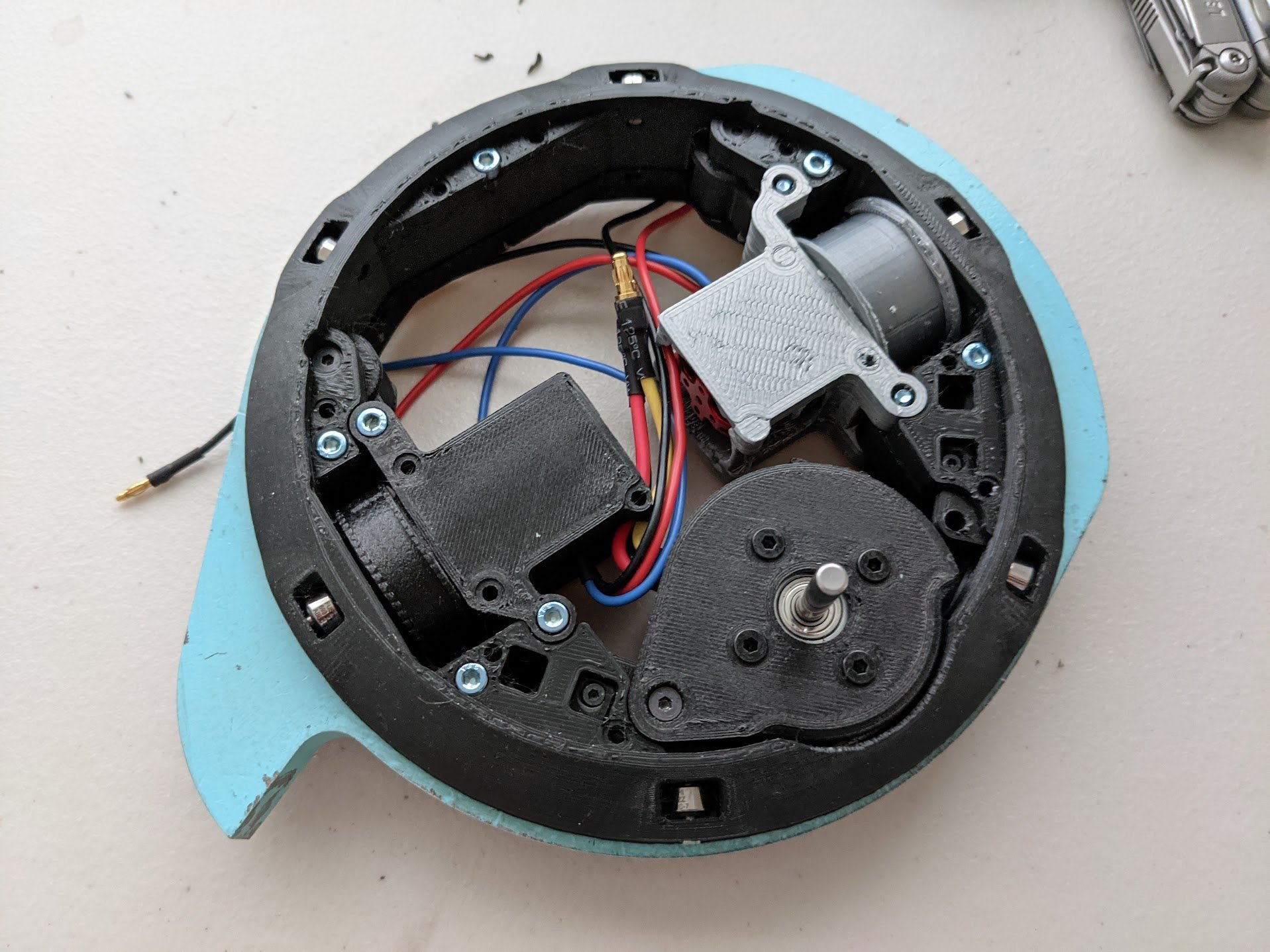
Battery exposed -> internal components arranged around smaller battery laying flat
Weapon motor jam -> replace linear movement on 4 bolts with rotational movement
Bearing impacts -> smaller bearings supported by steel shoulder bolts
Drive motor size -> replace COTS motor with custom thin & hollow wheel
Rim unbalanced -> make simple balancing jig
New Additions
Overall I was super excited about doing a new revision of the design, and feature creep got a hold of me and I changed two more things. The first was a simple switch from the previous imperial / inch bolts tapped directly into plastic to my new preferences of heat set inserts & metric hardware. The second (and ultimately fatal) new idea was to create a new weapon bearing support mechanism. Instead of the tried & true “measure twice, print once… and then again once you realize your printer isn’t accurate”, I designed a novel mechanism with adjustable radial locations for two of the bearings.
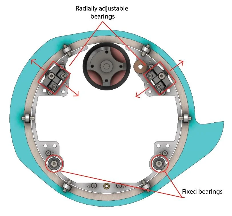
Bearing layout: note the 2 fixed bearings constraining the location of the circle and the 2 adjustable bearings preloading it
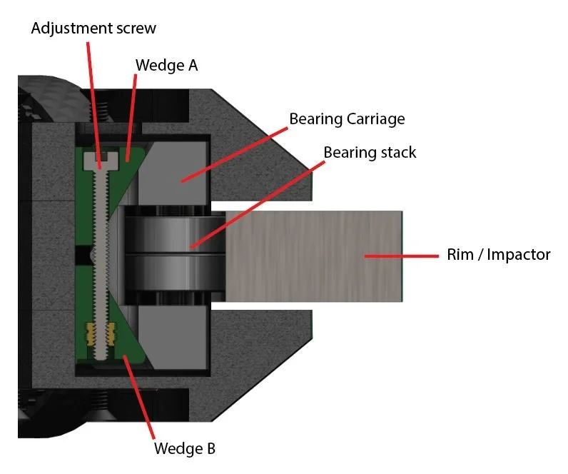
Adjustment screw pulls the two wedges (green) together, forcing the bearing carriage (white) radially into the rim
Overall Design Thoughts
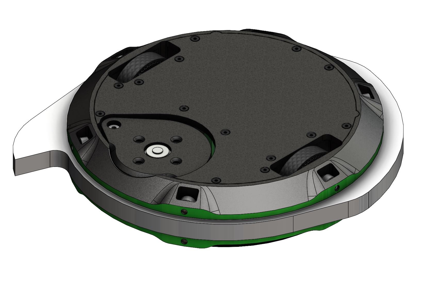
The design netted a really elegant design, which most all of the problems with v1 definitively fixed. There’s much more space due to the new motor & bearing solutions: enough to lay the same battery flat. The device is also much more modular, the drive motors and other components are much more easily replaceable.
Theoretically the 12 vertical support bearings (up from 6) and the 4 horizontal bearing locations should support the weapon rim much better.
Assembly & Manufacturing
Overall assembly went ok, there was originally a ton of tolerance and clearance issues, so it took multiple iterations to get things right. My first versions of this design actually still used a 2-part design, but the support material in the main rim surface was a doomed idea.
Failure Analysis
There were overall 2 problems that became apparent, even before fully assembling the unit
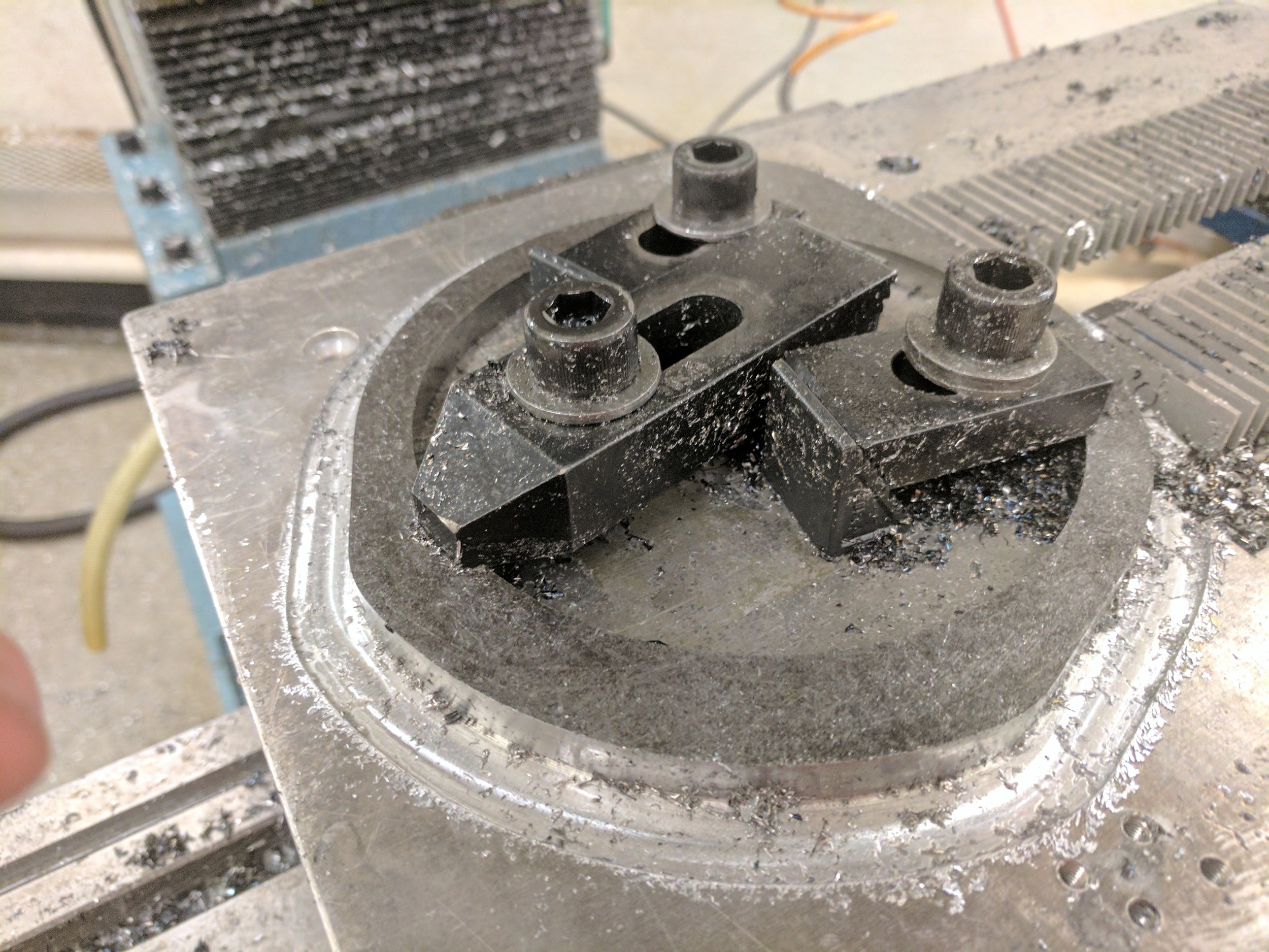
Bearing block failure / weapon friction: there was too much friction in initial versions of the design. The bearing blocks jammed easily and was prone to rotating, which unevenly loaded the bearings. Also, the smaller diameter of the bearings definitely didn’t help.
Space constraints for electronics: dispite being a lot more space-optimized than the v1 design, especially with regard to bearings and wheels, most of this was consumed by rotating the battery flat. This left only the space on top of the battery and between the drive motors to fit the electronics.
Going Forward
Space Solutions
There’s two main solutions to increasing the space for wiring in the design.
Remachine the ring to be bigger. Since I’m no longer 3D printer constrained, this is definitely the easy solution. However, I don’t have CNC mill access right now.
Create a direct drive motor solution. 2208 gimbals would fit and I tested them out but realized they’d need a sensored motor controller for low-end torque. This sounds like a fun learning experience so its a go!
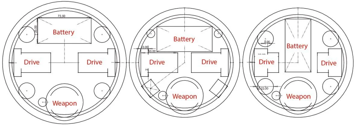
2 solutions to space: (left) larger machined ring gives more space, (center) baseline existing design, (right) direct drive hub motor w/ integrated drive ESCs & larger bearings
Version 3 Plans
The chart on the right overviews my planned changes for version 3. Overall the only difficult improvements will be the new ESC, and some titanium armor I’m hoping to add.
One typical problem with rim spinners is they suffer against wedges, so I want to test adding a removable wedge.

Version differences: hyphens indicate no changes from the previous version
Next blog post related to this will probably be a weapon bearing redesign or a motor controller design post depending on how long it takes to get ahold of STM microcontrollers or DRV83x3 motor drivers.