
Portable Power Supply Pt I: Design
In my search for economical, small shop tools for electromechanical product development (and the need to test my battlebot and custom motor controller projects) I found kralyn3d's fantastic mini power supply, which he details on his youtube and open-sources on grabcad. It manages to cram 0-36V 5A max output with control voltage and control current, along with a few other portability nice-to-haves, like a adjustable brightness screen, option to run off AC wall or DC battery power, and input voltage and current protection.
I really love this project and design: this component selection and 3D-printed enclosure successfully make an accessible design that is smaller and cheaper than similar-performing commercial units, but there are a number of things I wanted to change in my personal version. The following might come off as a scathing critique: but I actually love this project and wouldn’t have a personal power supply without it, so take it with a grain of salt.
The video Kralyn3D posted that inspired this project.
Reference Design Review
From a safety perspective, I have two main improvements to make which need to be mentioned first.
The AC power cable is unfused, attached to a screw terminal, not strain-reliefed in any way, and secured with hot glue. Any one of these is problematic when working with death-cables, but combined mean even a properly assembled device can expose a live, ungrounded 110V AC wire with a hard tug. I can avoid all these issues with $3 IEC C14 (standard 3-pin computer) socket for a detachable power cord.
On the reference design a separate AC power switch on the back is required to fully depower the unit. This means that an average user will likely leave the $12 Aliexpress AC to DC converter on unsupervised. The first unit I received has 5mm of permanent PCB warp, so I don’t trust this thing as far as I can flick it to remain safe to a degree I’d trust my apartment with. Additionally, in the event of a malfunction, the user would have to rush to turn off two switches, one of which is hidden on the backside of the unit. A side or front-mounted double throw double pole switch controlling both the AC input and DC output power would be a huge improvement.
From a usability perspective, it’s very nice that the user affordances are grouped on sides of the device: power inputs on the left, AC power switch on the back, fan control on the right, and power outputs on the front face, but this means all sides of the device need to be accessible during operation. I also think the dimensions can be optimized to take less horizontal and vertical space in exchange for more depth, which would reduce workbench space taken by matching the depth of common workshop devices. Additionally, the open sides and top limit the placement to areas with no particulate matter and prevent stacking, which is a problem in a makerspace or workshop. We can also eliminate the fold-out cable management brackets (despite their awesome functionality) in my version since the removable power cable gives similar functionality and is too thick to wrap tightly.
From an engineering perspective: I think I want to try getting away with massively downsize the cooling. Overcooling a prototype is always better than undercooling it, since cooling failures are messy and it’s really difficult to estimate the cooling required for an untested system. However, I’m willing to test it thoroughly (thermal camera, load resistors, oscilloscope, the works), and I’m hoping that I can testably prove that I can get away with >150W of power delivery with a massively downsized cooling solution. For a sanity check, we can compare this to laptop power supplies, where you can easily find smaller, fully enclosed designs delivering far more power. Theoretically, a 40mm fan providing active convection over exposed heatsinks is more than adequate to match a worst case single order of magnitude extra electrical inefficiency over our laptop baseline. On a side note, I also want to improve the DFA of the device: the originally design is assembled using machine screws self-tapped into plastic and adhesives, which reduce reparability and durability of the product.
From a design perspective, I personally would prefer something a little more minimalist and polished, but design is subjective and I only know enough about industrial design to know that I’m not qualified to lecture on it. I’d love to say I’m occam’s razoring a few features off (screw terminal input, usb port out) to avoid obvious flexibility tradeoffs, but in reality I just want to customize its function and looks to my preference.
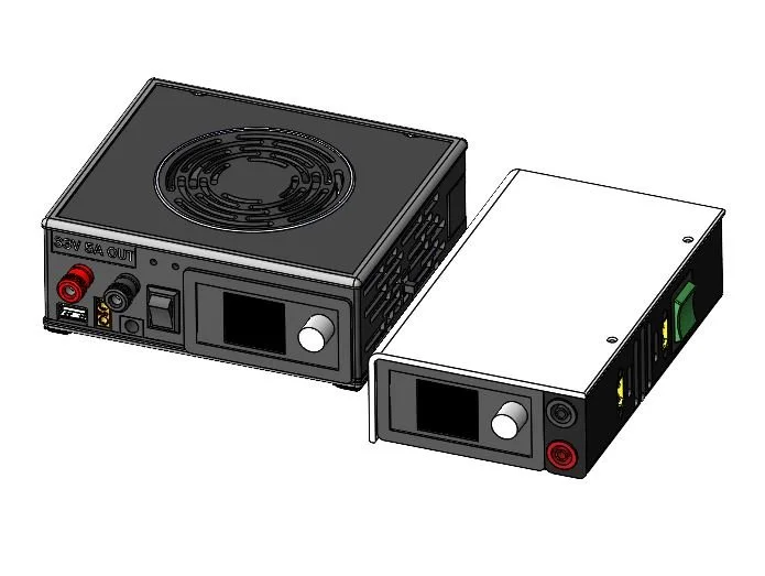
Reference design (left) vs Personal fork (right). Personal design has 35% smaller bounding box
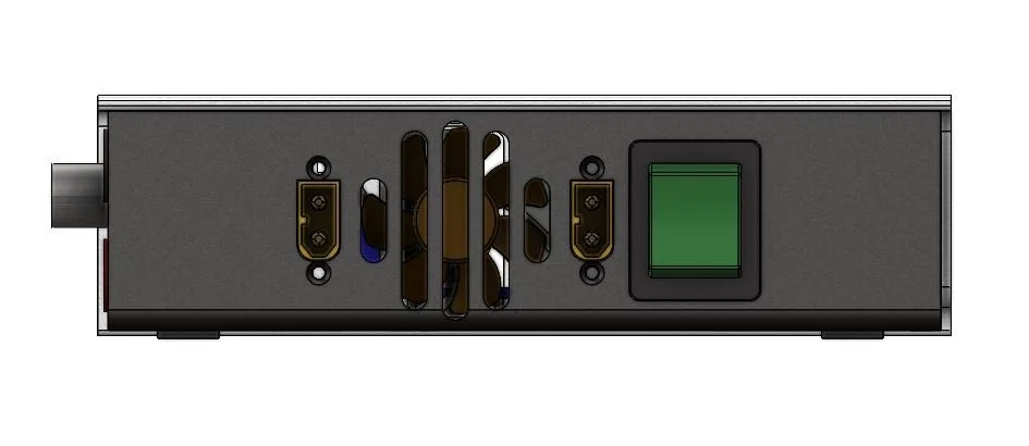
PSU Right side with ports labeled left-right: DC XT60 output, 40mm intake fan (filtered), DC XT60 input, Power Switch (lit, DC-AC-OFF)
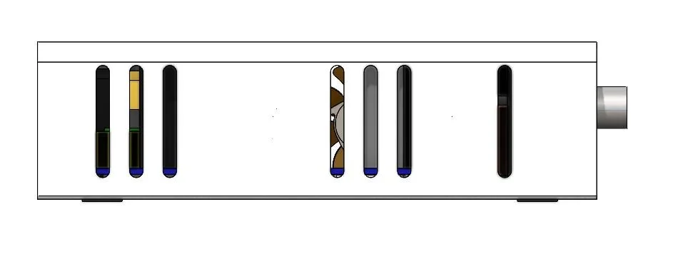
PSU Left side with exhaust grates aligned with major heatsinks
Main Changes Summary
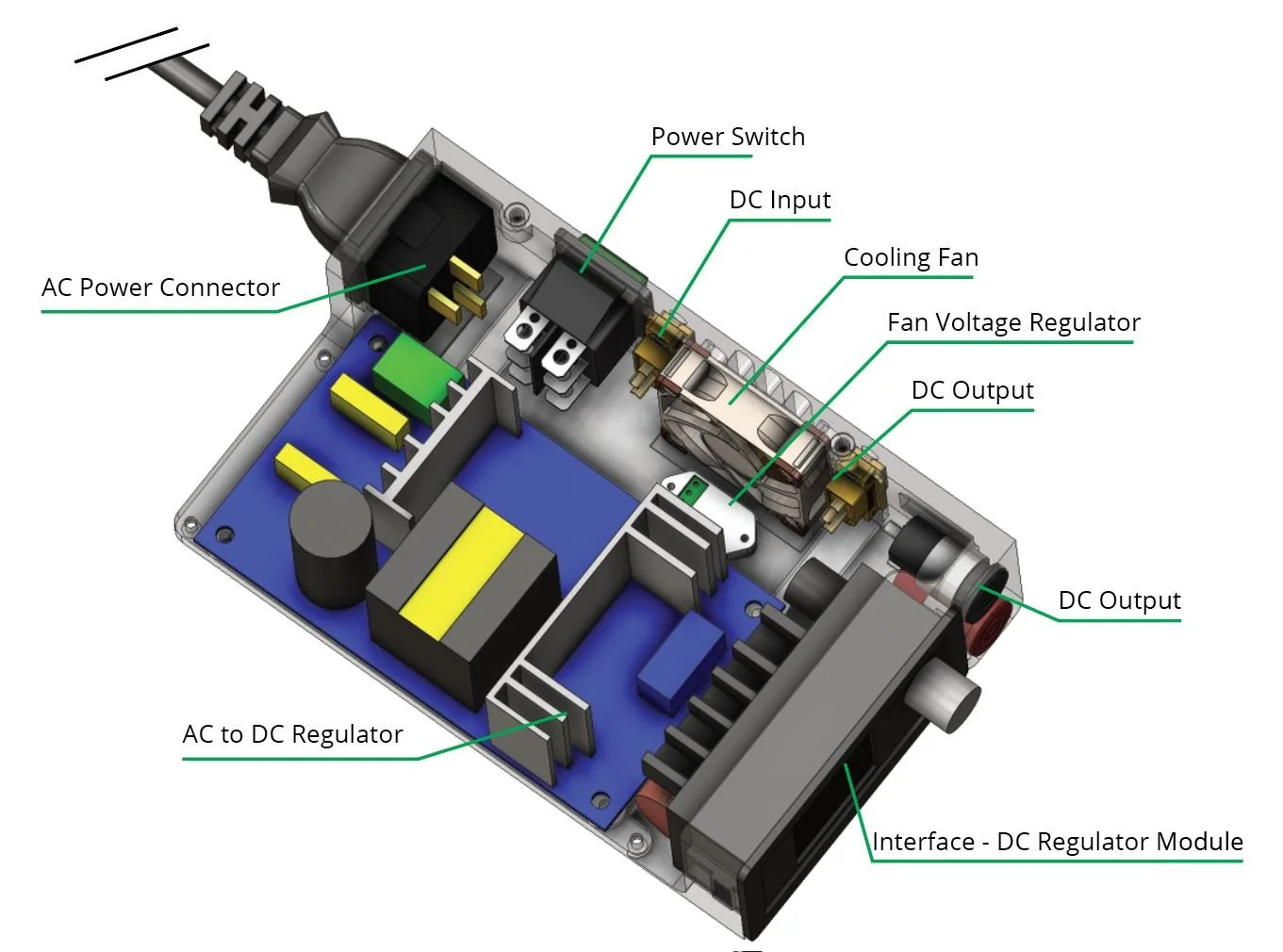
Internal layout diagram.
wide footprint with open top -> long narrow footprint with closed top for stacking
affordances grouped on all sides -> affordances grouped along front and right side
hardwired power cable -> fused IEC C14 socket
Separate AC input and DC output switches -> double pole double throw master switch
90mm top-mounted fan & open sides -> 40mm meshed side mounted fan & selectively opened sides to direct airflow to hot components
machine-bolt tapped plastic & adhesives -> brass heat set inserts
slightly reduced port compliment
A few random points that didn’t make it into the description so far:
Marbled white and chopped carbon-filled black PLA filaments were used to hide layer lines so it doesn’t read as heavily as a homemade
Ribbed reinforcements were used to reduce warping on thin components
Option to use 12V regulator or 4-
Next blog post I’ll document the assembly of my second unit, and go into the DFA considerations a bit more.