
Portable Power Supply Pt II: Assembly
In my last blog post I showed an open source portable power supply project I really liked, detailed some safety, engineering and design flaws it had, and proposed a version of the design optimized around my needs. I planned on building 2 for my personal use in developing wearable electronics and maybe a custom speed controller, and now that the design is complete and the components arrived I’m here to assemble them!
Since I have to assemble two of these I thought it would be good practice to do a little DFA process documentation.
I assembled one unit first, which took over 5 hours of fiddling, troubleshooting, and testing. With this knowledge and a goal of bringing the second unit under 2 hours, I drafted a Google sheet with assembly documentation, BOM, and a guide on wiring preparation.

Electrical component prep. Most panel-mounted components can be soldered before assembling into the frame. Only 3 joints need to be applied during assembly.
Assembly Prep
The first and longest stage of the assembly is the component preparation. The 3D prints postprocessing isn’t too bad, but cutting, stripping, and soldering all the wires to the panel-mount I/O takes over half of the total assembly time.
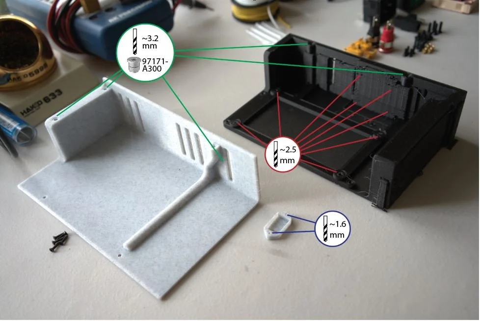
Mechanical component prep: after removing support material, some ‘reaming’ of holes is necessary to correct for 3D printer tolerances. Heat set inserts reduce wear caused by unscrewing the case.
Main Assembly
The second stage is the actual assembly and testing. I split this up into 3 stages, doing some connectivity and functionality tests in between each.
After assembling all AC components (wall plug, power switch, AC-DC converter), I stop to connectivity test the switch and ensure the AC-DC converter output voltage is around 36V.
After installing the DC input and fan, I stop to test fan voltage, airflow, and DC input switching.
The final assembly consists of installing the UI/buck regulator module, output ports, and top case. The fully assembled unit can be tested for OVP and OCP using the 4 built-in setpoints, which covers most of the voltage range.
I’ve learned that this style of test-as-you-go assembly is incredibly useful in avoiding full-system troubleshooting hell so common in DIY projects.
The timelapse video gives a brief overview of the 1 hour 50 minute assembly process.
Version Improvements
Between the first and second unit, the major improvement was the wiring. When assembling the first power supply I struggled to decide the order and length of wires and it shows.
After organizing wire lengths and connections in the google sheet and adding a few zip ties, the second unit ended up much cleaner and had much more leway for unplugging the UI. I also decided to implement an earth connection between the AC plug and the AC-DC converter on the second unit.

A 40mm wire connecting the AC-DC regulator to the UI strains the screw terminals and makes the UI fiddly to unplug

Second time around the wires going to the UI are all soldered and organized into 2 appropriate-length bundles.
Pain Points
There were 4 major pain points during assembly that I wasn’t able to improve between the first and second unit. 3 of these were solder joints that weren’t done before in-frame assembly and the final was a connector that was rather annoying to tighten down.

The AC wall plug must be mounted from the outside, which means this optional wire to earth must be soldered after the fact. This can be fixed with a crimped 1/8” ring terminal.

Both the AC plug and power switch are inserted from the outside, and therefore must be soldered post-assembly.

The XT60E-M is actually small enough to fit through the hole of the switch, so this could have been avoided.

These banana plugs with their smooth, notched nuts are a nightmare to screw in using a flathead screwdriver. I might add a bit more clearance if making more.
Scale Improvements
If assembling and selling these at a scale of ~100 units (not economically viable as proven later)
Optimized 3D print settings & supports (potentially multimaterial dissolvable PVA) to reduce support removal time and eliminate the need for postprocess ‘reaming’ of holes
Provide 2-5mm more clearance on the banana connectors and bend some steel wire into a teeny-tiny hook wrench for tightening the castled nuts
Soldering pot for quickly tinning wires and panel mount contacts
Automated wire cutting and stripping by means of Bstrip, using standard 20AWG PVC insulated wire
Crimped ferrules / ring terminals to improve screw terminal connection and eliminate soldering ‘pain points’ discussed above
Higher quality heat shrink tubing in combination with proper heat gun
Doing a bunch of these in parallel with a few of the above improvements implemented I’d estimate would halve the assembly time per box. With the BOM cost of $95 reduced to $70 via Aliexpress / bulk sourcing instead of Amazon, factoring in fixed costs of ~$1k for the above tooling ($10 per unit), $2 of custom packaging and $10 of shipping and gives a minimum price of $100. Add in a bit of margin and this design is saleable for around $150.
Competitive Viability
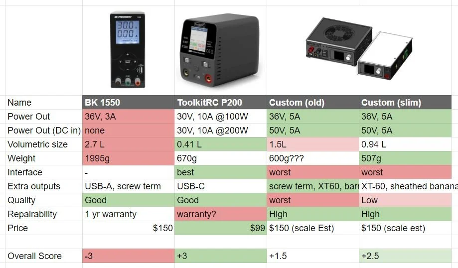
At that price point its only compact competitor from traditional engineering brands is the BK Precision 1550, which it compares to very favorably, offering 60% more current output, more flexibility, and a much smaller form factor at the expense of a smaller and more fiddly UI and reduced build quality.
However, the ToolkitRC P200 power supply exists. It sacrifices a tiny bit of power delivery for a much better UI, while being than 50% smaller volumetrically and 33% cheaper. Unless you really like the flat, stackable design or need the XT60 output, the ToolkitRC is the clear choice from specs alone and reviews well to boot.
Ultimately this means the design isn’t commercial viable (it would honestly be a shock if something this unoptimized was) but it’s still a good build and I’m glad I can contribute to an open-source design, as I’ll be posting the files and instructions with MIT license after testing it more thoroughly.

Fully assembled units (left unit with top frame off)
I’ll probably make a third and final blog post about these once I get access to / buy an oscilloscope to test the performance of the voltage and current control. I’ve found a few people who have done basic ripple tests on similar units, but I’m more concerned about voltage & current overshoot.